Supercharge Your Innovation With Domain-Expert AI Agents!

Vacuum pug mill

a vacuum and pug mill technology, applied in the field of vacuum mills, can solve the problems of air entrapment, adversely affecting throwing operations, ruined products, etc., and achieve the effect of enhancing communication of vacuum

Active Publication Date: 2017-01-05
PAZ JARED
View PDF3 Cites 1 Cited by
  • Summary
  • Abstract
  • Description
  • Claims
  • Application Information

AI Technical Summary

Benefits of technology

This configuration improves air extraction during the mixing process, preventing air entrapment and enhancing the homogeneity and workability of the clay, thus improving the quality of ceramic products.

Problems solved by technology

Air entrapped in the clay when fired can expand to ruin the article manufactured.
Also, entrapped air can adversely affect throwing operations as it makes the clay “short” and hard to work with.
It remains that material being pugged can still overwhelm the communication port and interrupt the application of vacuum in the mixing chamber.

Method used


Image

  • Vacuum pug mill
  • Vacuum pug mill
  • Vacuum pug mill

Examples


Embodiment Construction

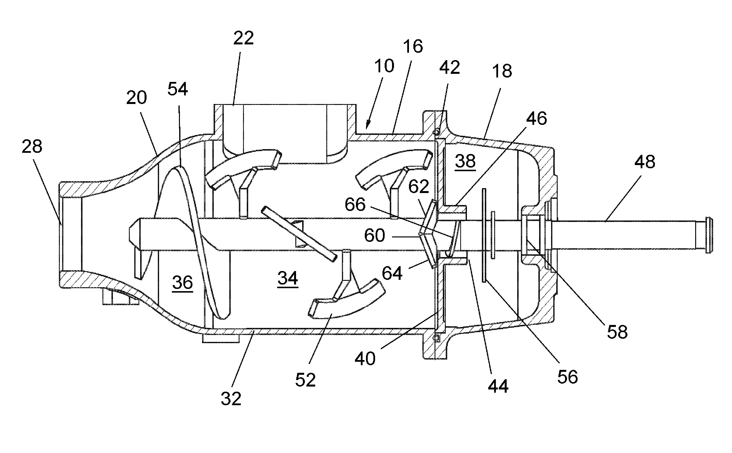
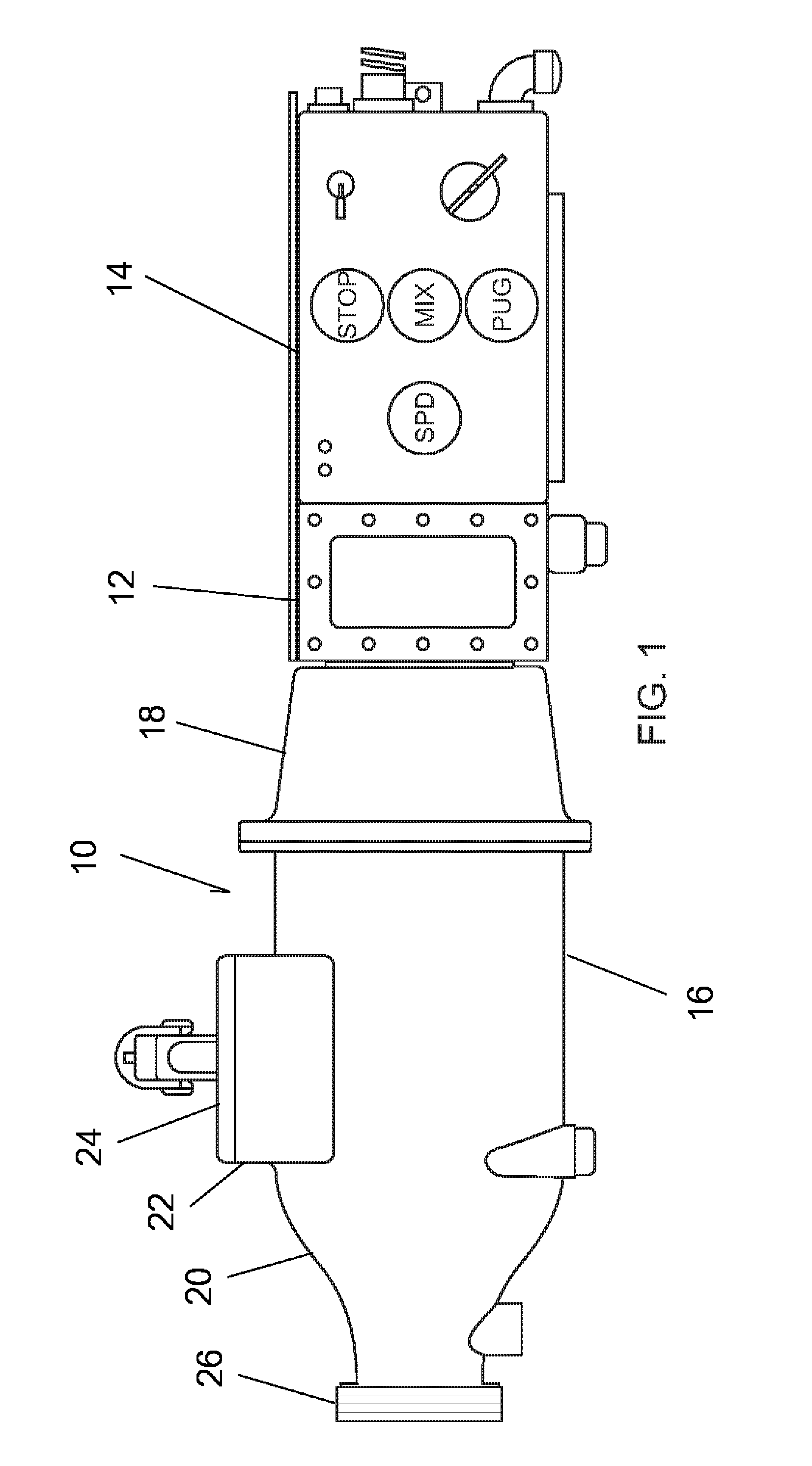
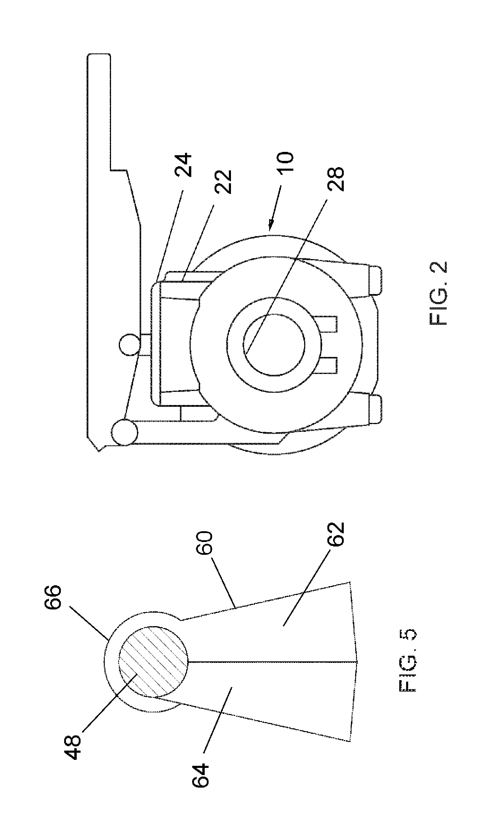
[0015]Turning in detail to the drawings, a pug mill is illustrated in FIGS. 1 and 2. The assembly includes a sealable chamber housing assembly 10, a gear casing 12 and a power box 14. The housing assembly 10 encloses a sealable chamber defined by a mixing chamber housing 16 and a vacuum chamber housing 18. The mixing chamber housing 16 includes a reduction cone 20 at the end of the housing 16, an access port 22 and a hatch cover 24 for access to the interior of the sealable chamber. A cover 26 covers an extrusion port 28 at the end of the reduction cone 20 for selectively sealing the sealable chamber. The gear casing 12 and power box 14 provide controls, a drive motor and gearing for driving a shaft extending through the vacuum chamber housing 18 and mixing chamber housing 16. A source of vacuum (not illustrated) is provided in communication with the vacuum chamber housing 18 through the power box 14 as well. The vacuum chamber housing 18 also includes an access port and cover to al...


PUM

PropertyMeasurementUnit
homogeneityaaaaaaaaaa
vacuumaaaaaaaaaa
rotationaaaaaaaaaa

Abstract

A pug mill having a housing and a cantilevered shaft extending through the housing includes, in seriatim, a vacuum chamber, a wall, a mixing chamber and a reduction cone. A communication port about the shaft is positioned in the wall between the vacuum chamber and the mixing chamber. Vacuum can be maintained within the mixing chamber by air passing through the port. An auger associated with the shaft forces clay toward the reduction cone. This creates a seal for maintaining vacuum within the mixing chamber and extrudes cylindrical blocks of conditioned clay without significant air bubbles. A deflection plate rotating with the shaft and a spiral element about the shaft keep the communication port clear. The shaft is eccentrically mounted. The dividing wall is removable.

Description

CROSS-REFERENCE TO RELATED APPLICATIONS[0001]This is a continuation of U.S. patent application Ser. No. 14 / 534,672, filed Nov. 6, 2014, the disclosure of which is incorporated herein by reference.BACKGROUND OF THE INVENTION[0002]The field of the present invention is pug mills for mixing and conditioning clay for ceramics.[0003]Pug mills are designed for producing clay conditioned for the manufacture of ceramics. The mills typically are used to mix clay powder and water or rehydrate, remix and / or recondition existing clay. Powders and water may also be mixed with existing clay to form a homogeneous product. The clay, once mixed, is most conveniently extruded through a reduction cone to form cylindrical or rectangular blocks also known as pugs.[0004]Pug mills upon which the present design is based are disclosed in U.S. Pat. No. 4,322,169 entitled CLAY MIXING APPARATUS and U.S. Pat. No. 5,716,130 entitled VACUUM PUG MILL, the disclosures of which are incorporated herein by reference in...

Claims


Application Information

Patent Timeline
Patent Type & Authority Applications(United States)
IPC IPC(8): B01F13/06B01F7/08B28B17/02B01F7/00
CPCB01F13/06B28B17/02B01F7/08B01F7/00416B28C1/16B28C1/225B28C5/143B01F23/53B01F27/0723B01F27/0726B01F27/2123B01F27/70B01F33/70B01F2035/351B01F35/333B01F27/72B01F27/1143B01F27/1921B01F2101/28
Inventor PAZ, JARED
Owner PAZ JARED
Features
  • R&D
  • Intellectual Property
  • Life Sciences
  • Materials
  • Tech Scout
  • Unparalleled Data Quality
  • Higher Quality Content
  • 60% Fewer Hallucinations
Learn More