System and methods for automatically landing aircraft

a technology of automatic landing and aircraft, applied in the direction of process and machine control, using reradiation, instruments, etc., can solve the problems of aircraft diverting from the intended host platform, multi-million dollar assets having to be ditched at sea, and based landing systems susceptible to component failures

Active Publication Date: 2017-01-05
AURORA FLIGHT SCI CORP
View PDF6 Cites 30 Cited by
  • Summary
  • Abstract
  • Description
  • Claims
  • Application Information

AI Technical Summary

Benefits of technology

[0014]In other embodiments, the present invention is directed to a method of landing an aircraft on a vessel, comprising the steps of: providing an aircraft in flight at a VRODW location aft of the vessel; approaching the vessel from the VRODW; identifying a landing area of the vessel using LIDAR; hovering the aircraft above the landing area; descending to the landing area; and landing the aircraft on the vessel. In some embodiments, the LIDAR is scanning or flash LIDAR. In some embodiments, the landing area is designated on the vessel by a symbol. In some embodiments, the symbol is a circle, a cross, an H-shape, or other conventional symbols used on vessels to designate a landing area. In some embodiments, the method further comprises identifying a touchdown marker within the landing area.

Problems solved by technology

Present day aircraft performing autonomous landings on naval vessels rely on a ship-mounted, radar-based landing system that is susceptible to component failures.
Such a failure would require the aircraft to divert from the intended host platform to another radar-landing-system-equipped vessel or land-based facility.
If an acceptably equipped alternate vessel or land facility is out of range or unavailable, a multi-million dollar asset would have to be ditched at sea.
Moreover, existing methods fail to address the complete problems of locating and approaching the ship from a distance, detecting the touchdown point and safely positioning the aircraft over the touchdown point, and tracking the touchdown point to touchdown.
Finally, existing methods rely on ship-mounted, radar-based landing equipment which may provide unnecessary risks and limitations.

Method used


Image

  • System and methods for automatically landing aircraft
  • System and methods for automatically landing aircraft
  • System and methods for automatically landing aircraft

Examples


example 1

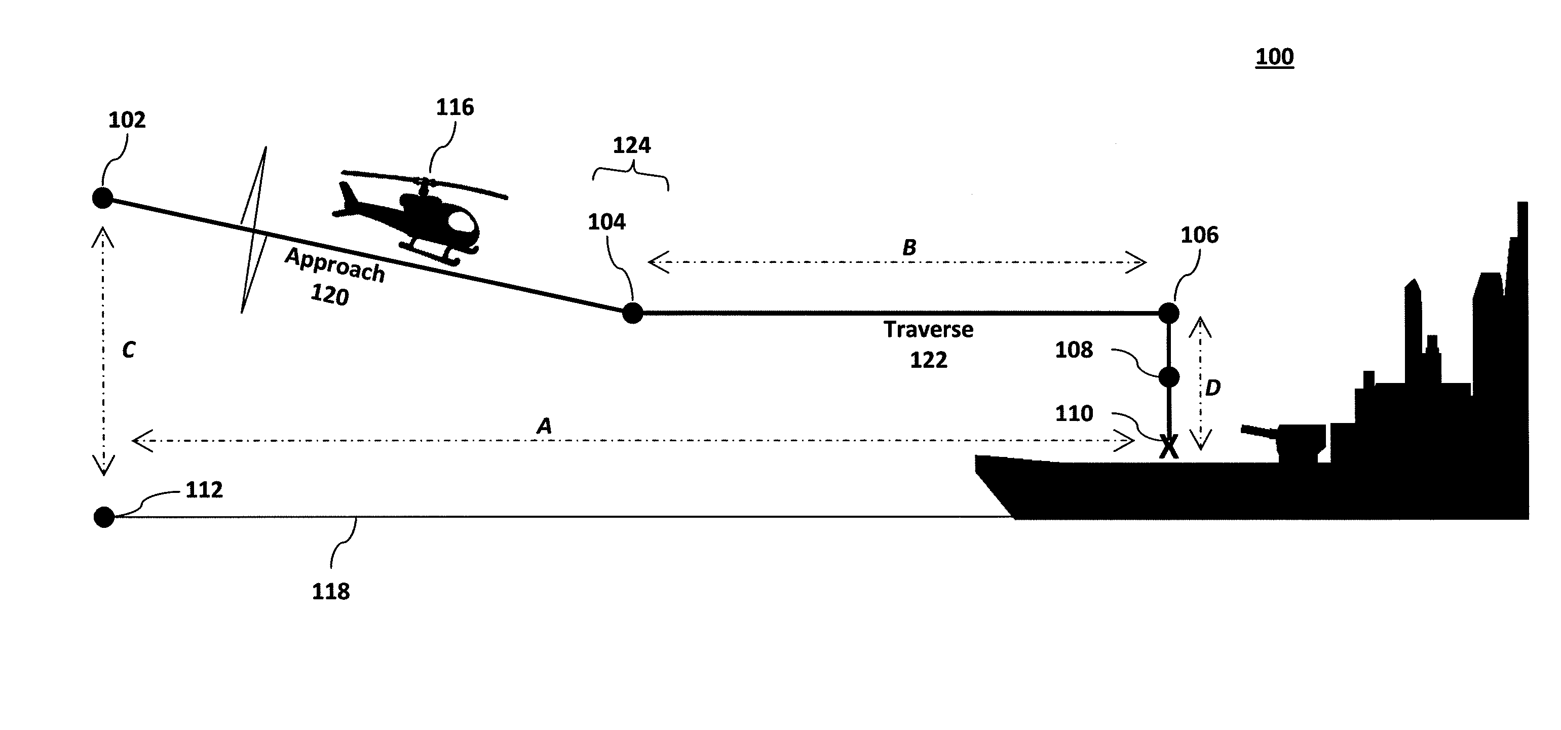
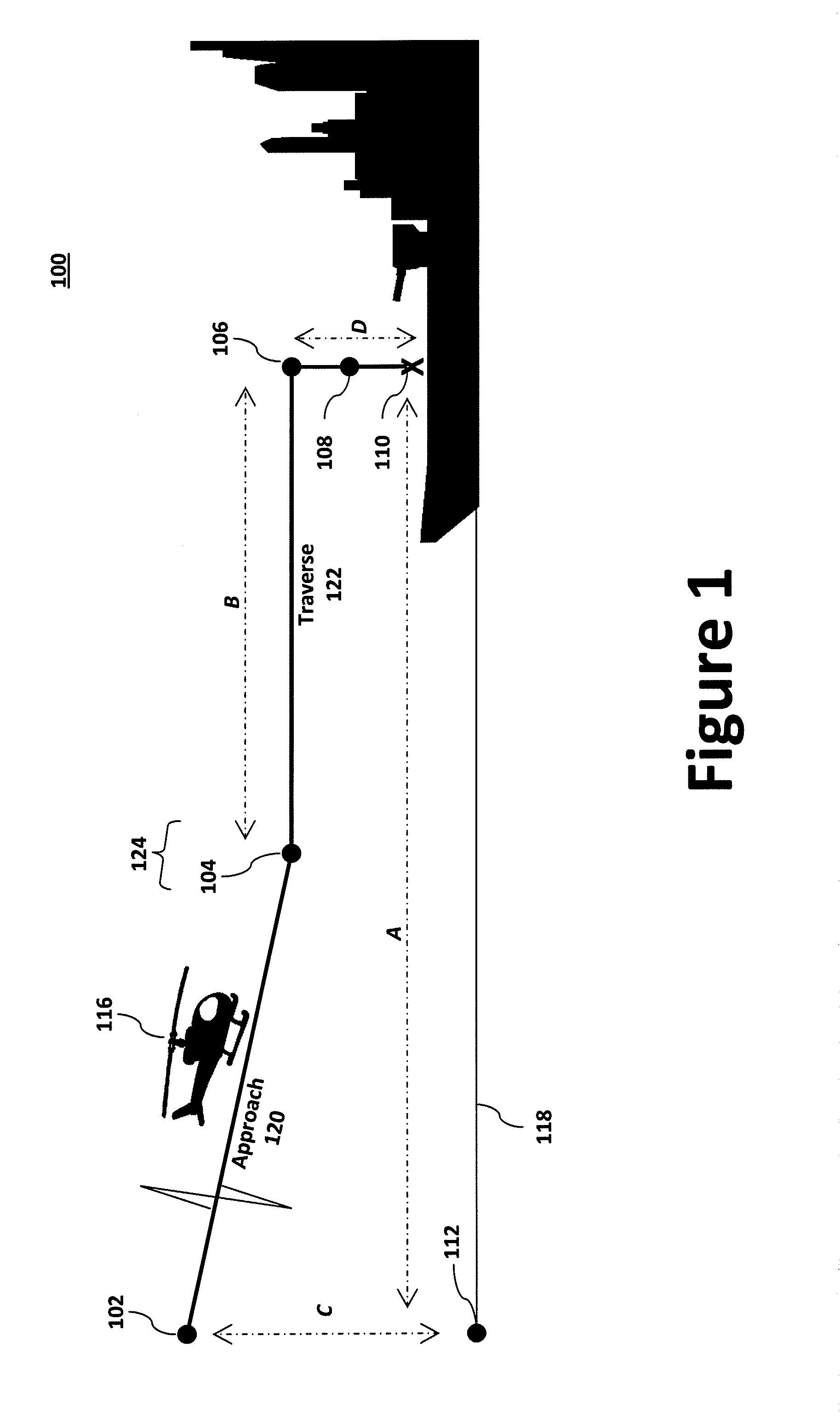
[0057]An example landing sequence 100 is illustrated in FIG. 1. The landing operation 100 starts at the initialization point 102 with the aircraft 116 in flight at an altitude C (e.g., 300 to 1000 feet, more preferably 400-700 ft, even more preferably 500 ft) and a distance A (e.g., 1 to 1.5 nautical miles) within 45° of the stern of the vessel 114. Using one or more sensors, the aircraft 116 may determine, or receive, the vessel 114 range and vessel 114 bearing relative to the aircraft 116. The aircraft 116 may approach the vessel 114 at a predetermined closing speed (e.g., 40 knots with a glide angle of about 3°). Using a computer-implemented algorithm coupled with one or more onboard sensors, the aircraft 116 can determine the aircraft groundspeed and aircraft position in a local coordinate frame. Similarly, the aircraft 116 may determine vessel position and vessel velocity in the local coordinate frame from the vessel range, vessel bearing, aircraft groundspeed, and aircraft pos...

example 2

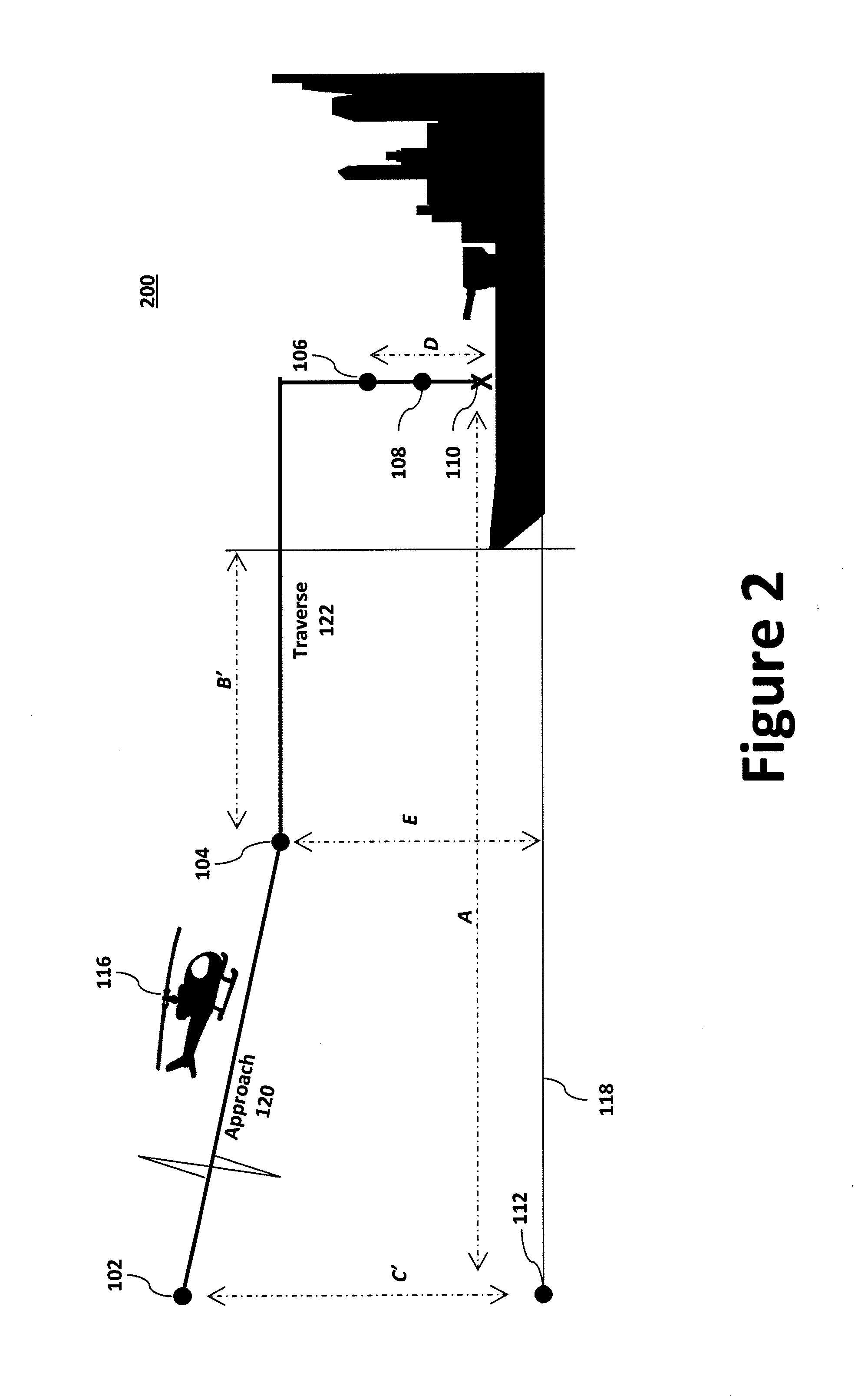
[0059]Another technique in providing a VTOL landing system that can operate on a variety of vessels without knowledge of vessel type includes the generalization of the initialization point 102 and Perch Point 104 in the landing sequence into locations that are independent of vessel geometry. FIG. 2 illustrates a modified landing sequence 200, which is similar to that shown in FIG. 1, but with a change in the specification of the initialization point 102 and Perch Point location 104. While the baseline Perch Point 104 was previously specified to be distance D above the deck in landing sequence 100, such an approach may be vessel-dependent since the deck height can vary from vessel to vessel. Therefore, a generalized Perch Point 104 of landing sequence 200 may be specified to be distance E (e.g., 70 ft) above sea level 118. This eliminates dependency on deck height while ensuring that the Perch Point 104 will be sufficiently high above the deck of a given vessel 114. For example, whil...


PUM


Abstract

The present invention is directed to methods of determining a vessel-relative off-deck waypoint (VRODW) location comprising the steps of providing an aircraft in flight; determining vessel range and vessel bearing relative the aircraft; and determining the VRODW location using the range and bearing measurements of the vessel. The present invention is further directed to methods of landing an aircraft on a vessel.

Description

FIELD OF THE INVENTION[0001]The present invention is directed to methods of determining a vessel-relative off-deck waypoint (VRODW) location comprising the steps of providing an aircraft in flight; determining vessel range and vessel bearing relative to the aircraft; and determining the VRODW location using the range and bearing measurements of the vessel. The present invention is further directed to methods of landing an aircraft on a vessel.BACKGROUND OF THE INVENTION[0002]Present day aircraft performing autonomous landings on naval vessels rely on a ship-mounted, radar-based landing system that is susceptible to component failures. Such a failure would require the aircraft to divert from the intended host platform to another radar-landing-system-equipped vessel or land-based facility. If an acceptably equipped alternate vessel or land facility is out of range or unavailable, a multi-million dollar asset would have to be ditched at sea.[0003]Methods exist for measuring the relativ...

Claims


Application Information

Patent Timeline
Patent Type & Authority Applications(United States)
IPC IPC(8): B64D45/04G05D1/10G05D1/04G01S13/91G01S17/88
CPCG01S7/411G05D1/0684G01S17/933G01S7/4802G01S13/60G01S13/86G01S13/865G01S13/882G01S13/913G01S13/935G01S17/86B63B35/50B64D45/04G01S17/88
Inventor LIM, EDWARD
Owner AURORA FLIGHT SCI CORP
Why Eureka
Try Eureka