
ESD protected tubing for removing charge from lumen

Active Publication Date: 2017-01-05
AGILENT TECH INC
View PDF15 Cites 4 Cited by
  • Summary
  • Abstract
  • Description
  • Claims
  • Application Information

AI Technical Summary

Benefits of technology

[0019]In an embodiment, the tubing comprises an optically transparent section configured for enabling an external inspection of the conducted fluid within the at least one lumen. For example, the entire tubing with the exception of the electrically conductive material can be made of an optically transparent material through which a user can inspect the fluid flowing in the lumen. For example in terms of liquid chromatography, the presence of air bubbles or the like in the flowing fluid may be indicators of a problem in the liquid separation setup, so that the option of monitoring the fluid flow may be highly advantageous.
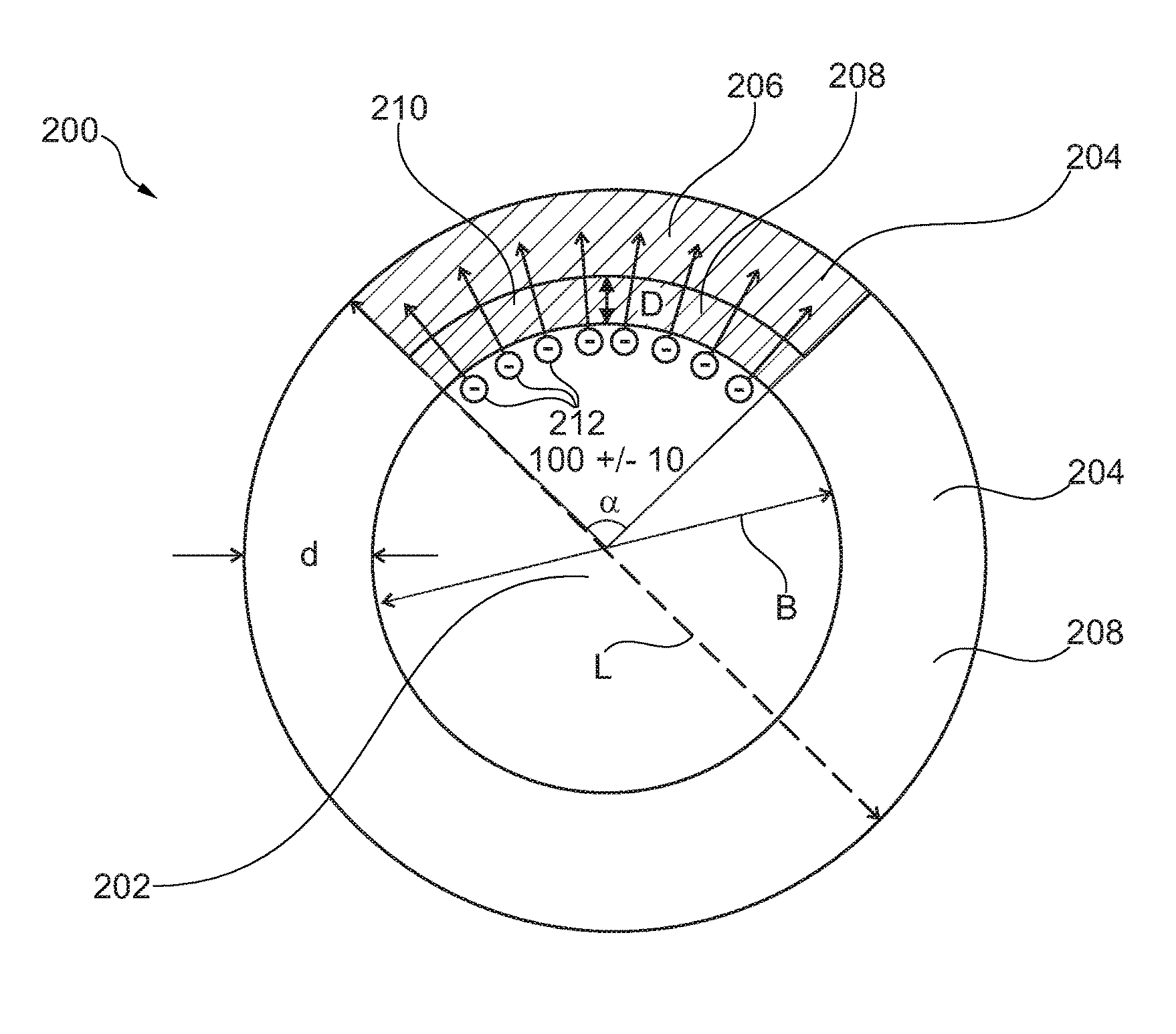
[0020]In an embodiment, the entire lumen is delimited by the optically transparent section, and the electrically conductive section is arranged to surround part of the optically transparent section so that the electric charge is at least partially electrically conducted from the at least one lumen via the optically transparent section to the electrically conductive section. Many polymers show at the same time an optically transparent property as well as an inertness against chemical fluids (such as solvents for liquid chromatography) and biological fluids (such as fluidic samples to be separated by liquid chromatography) and is therefore particularly suitable to be used as the basis for the formation of the tubing. Only the locally required electrical conductivity of the tubing is then provided by the electrically conductive section. A corresponding tubing can be manufactured with reasonable effort and provides all properties desired by a user.
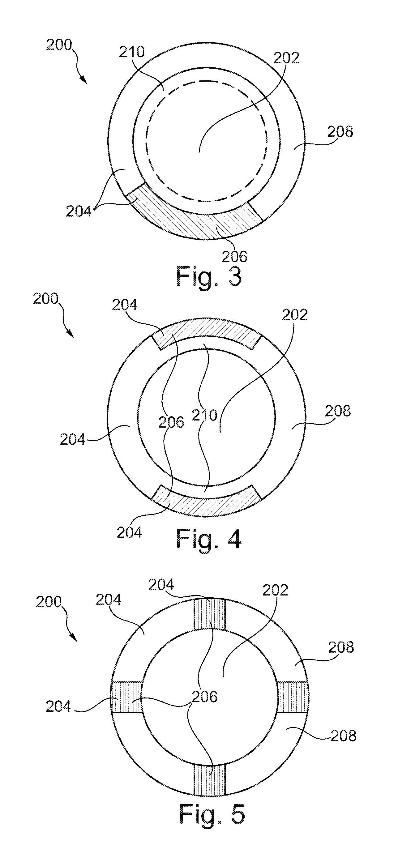
[0021]In an embodiment, the electrically conductive section is configured as an axially extending annular segment of the tubing. Forming the electrically conductive section as an axially continuous structure allows to transport the generated charge carriers towards an electric ground potential, even over a relatively large distance parallel to the flowing fluid. By providing the electrically conductive s

Problems solved by technology

However, when fluid, in particular at least partially non-polar fluid, flows through such a conduit or tubing in particular with high passing speed of liquid molecules through a gi

Method used


Image

  • ESD protected tubing for removing charge from lumen
  • ESD protected tubing for removing charge from lumen
  • ESD protected tubing for removing charge from lumen

Examples


Example

[0055]The illustration in the drawing is schematically.

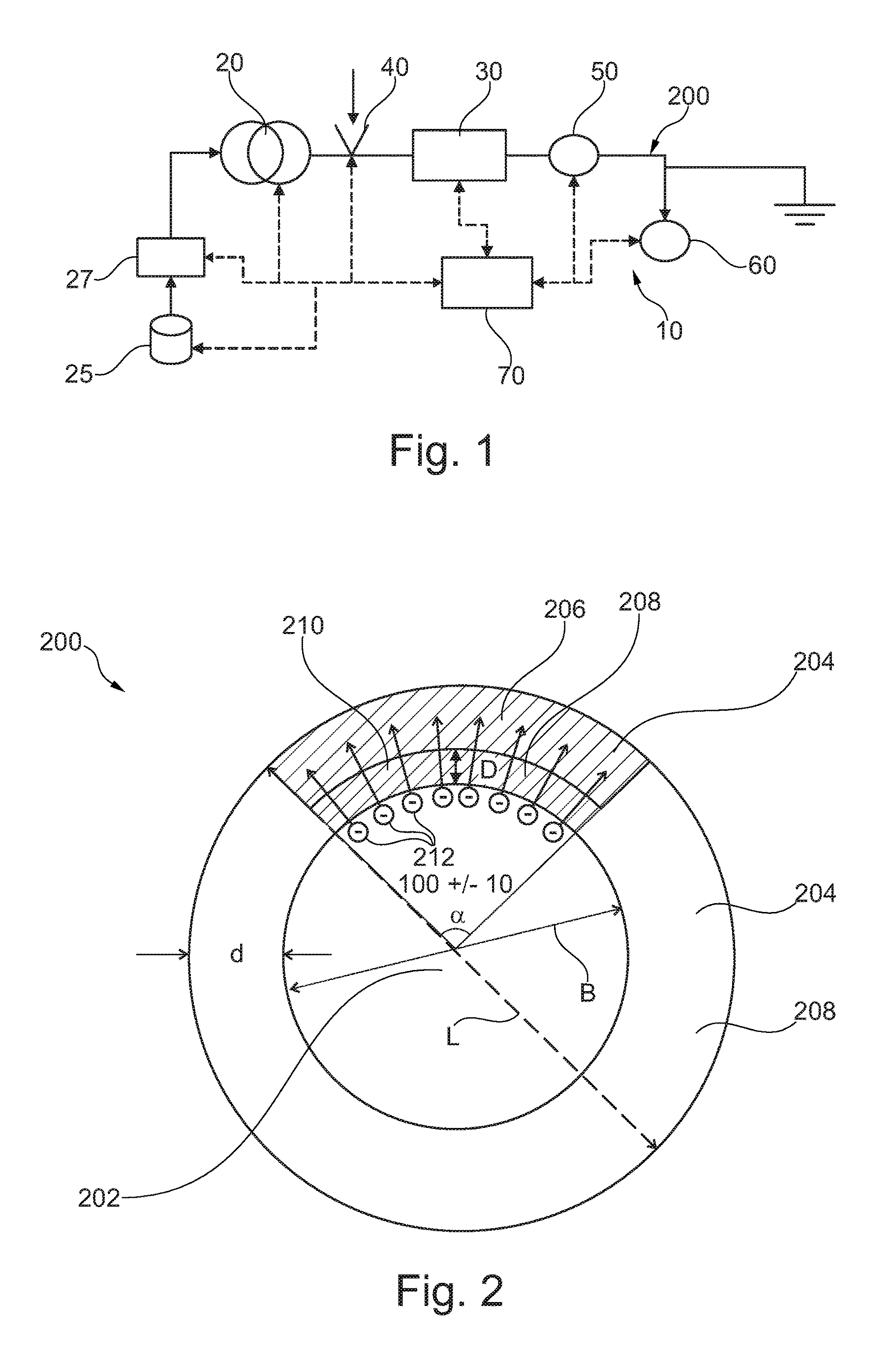
[0056]Referring now in greater detail to the drawings, FIG. 1 depicts a general schematic of a liquid separation system 10. A pump 20 receives a mobile phase from a solvent supply 25, typically via a degasser 27, which degasses and thus reduces the amount of dissolved gases in the mobile phase. The pump 20—as a mobile phase drive—drives the mobile phase through a separating device 30 (such as a chromatographic column) comprising a stationary phase. A sampling unit 40 can be provided between the pump 20 and the separating device 30 in order to subject or add (often referred to as sample introduction) a sample fluid into the mobile phase. The stationary phase of the separating device 30 is configured for separating compounds of the sample liquid. A detector 50 is provided for detecting separated compounds of the sample fluid. A fractionating unit 60 can be provided for outputting separated compounds of sample fluid.

[0057]While the...


PUM


Abstract

An electrostatic discharge protected device for conducting a fluid through at least one lumen includes a tubing having a hollow interior defining the at least one lumen. The tubing includes an electrically conductive section configured for conducting electric charge, generated within the at least one lumen when the fluid flows through the at least one lumen, away from the at least one lumen.

Description

BACKGROUND ART[0001]The present invention relates to an electrostatic discharge protected device for conducting a fluid through at least one lumen, to a fluid separation apparatus, and to a method of conducting a fluid through at least one lumen with electrostatic discharge protection.[0002]U.S. Pat. No. 3,580,983 discloses that nonsparking tubes can be fabricated from polymers which are susceptible of acquiring an electrostatic charge upon frictionally contacting other bodies or surfaces such as textile elements. U.S. Pat. No. 3,580,983 furthermore discloses a conductive line tubing manufactured by extruding from a mass of flexible plastic material an elongated tube contemporaneous with the extrusion of an elongated electrically conductive plastic filament that is secured to said tube in superimposed relationship piggyback arrangement.[0003]U.S. Pat. No. 5,614,589 discloses a transparent, antistatic thermoplastic composition and methods of making the same.[0004]In liquid chromatogr...

Claims


Application Information

Patent Timeline
IPC IPC(8): G01N30/60B01D15/24F16L11/127G01N30/80G01N30/74
CPCB01D15/24F16L11/127G01N30/74G01N30/80G01N30/6052G01N2030/027
Inventor ZIEGLER, TONYFALK-JORDAN, STEFAN
Owner AGILENT TECH INC
Learn More