Shower head water regulator

a technology of water regulator and shower head, which is applied in the field of shower head, can solve the problems of water waste, water shortage, and many wastes of water, and achieve the effect of convenient installation, use and maintenan

Inactive Publication Date: 2017-01-12
BURNS STEPHEN S
View PDF4 Cites 11 Cited by
  • Summary
  • Abstract
  • Description
  • Claims
  • Application Information

AI Technical Summary

Benefits of technology

[0008]A need exists for an improved showerhead which is self-contained and designed to be a plug-and-play replacement for almost any showerhead in the world. The disclosed and other embodiments according to this invention provide a solution to the above-referenced problems by providing a showerhead that automatically regulates water flow and is easy to install, use, and maintain.

Problems solved by technology

For example, many parts of the world suffer from drought conditions resulting in shortages of drinking water for their populations.
However, as much as half of this water is often wasted and flows down the shower drain without ever being used.
In this regard, this waste of water occurs, for example, when the individual using the shower is temporarily not standing beneath the showerhead while the water is running.
This wasteful misuse of water results in the unnecessary depletion of the water supply, and leads to unnecessarily excessive water bills that are disproportionate to the amount of water actually used.
These early sensor schemes, particularly the scheme disclosed in the '673 patent, suffer from a limitation, namely, that because the sensors are particularly sensitive to the distance between the showering person and the showerhead, the detection scheme performs poorly for people not of the optimal height.
These, however, generally rely on significantly more expensive hardware.
Such conventional systems suffer from additional drawbacks, such as requiring complicated installation.
In addition, existing solutions may fail to maintain a constant temperature between turning the water flow off and on.

Method used


Image

  • Shower head water regulator
  • Shower head water regulator
  • Shower head water regulator

Examples


Embodiment Construction

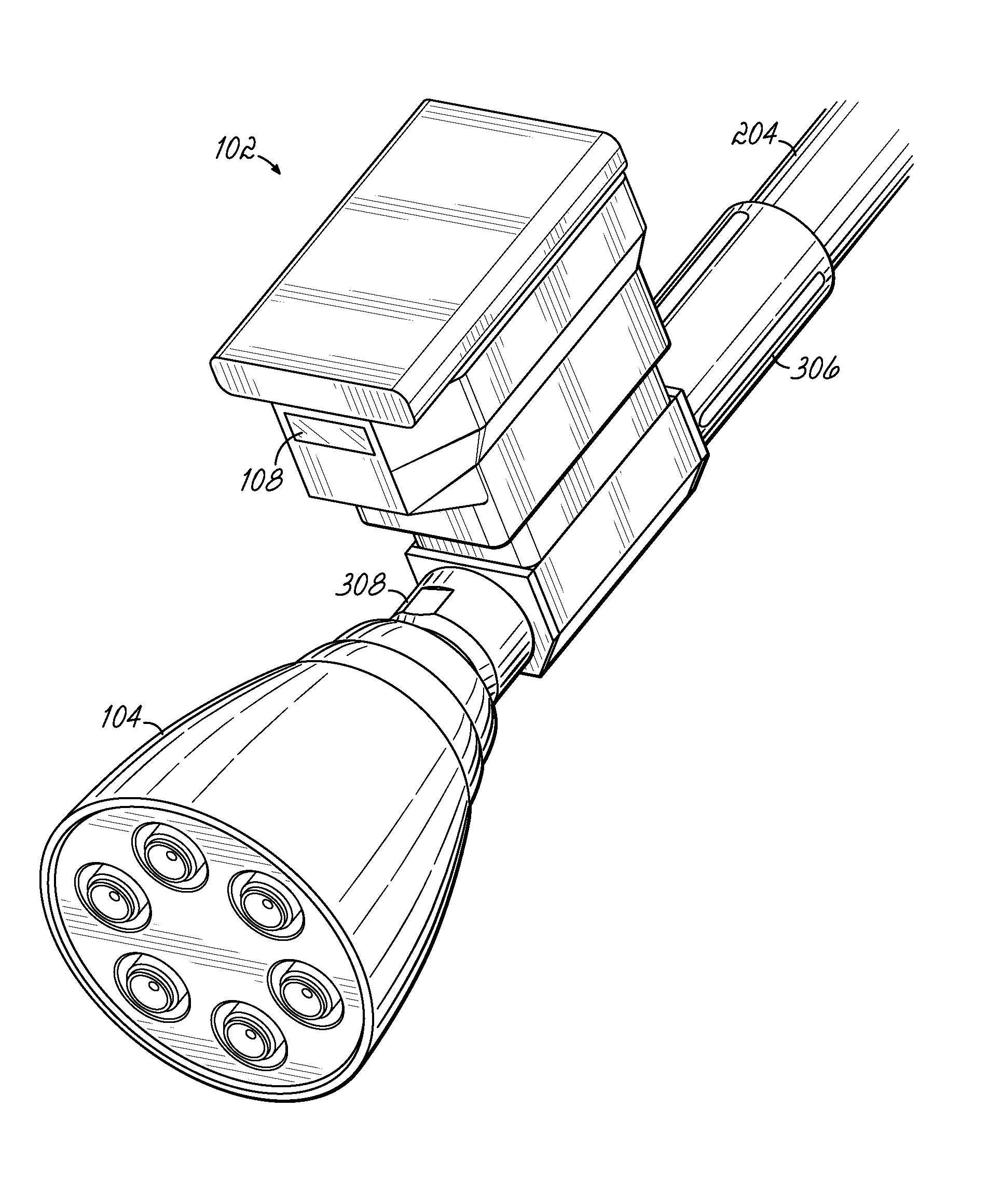
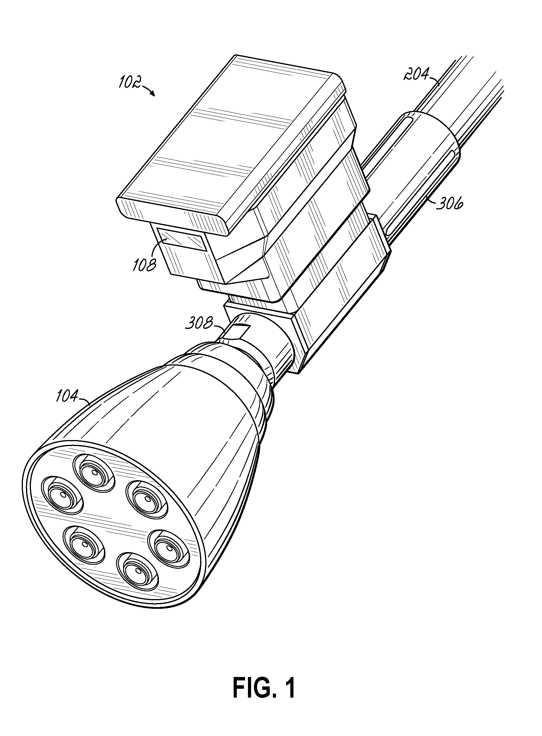
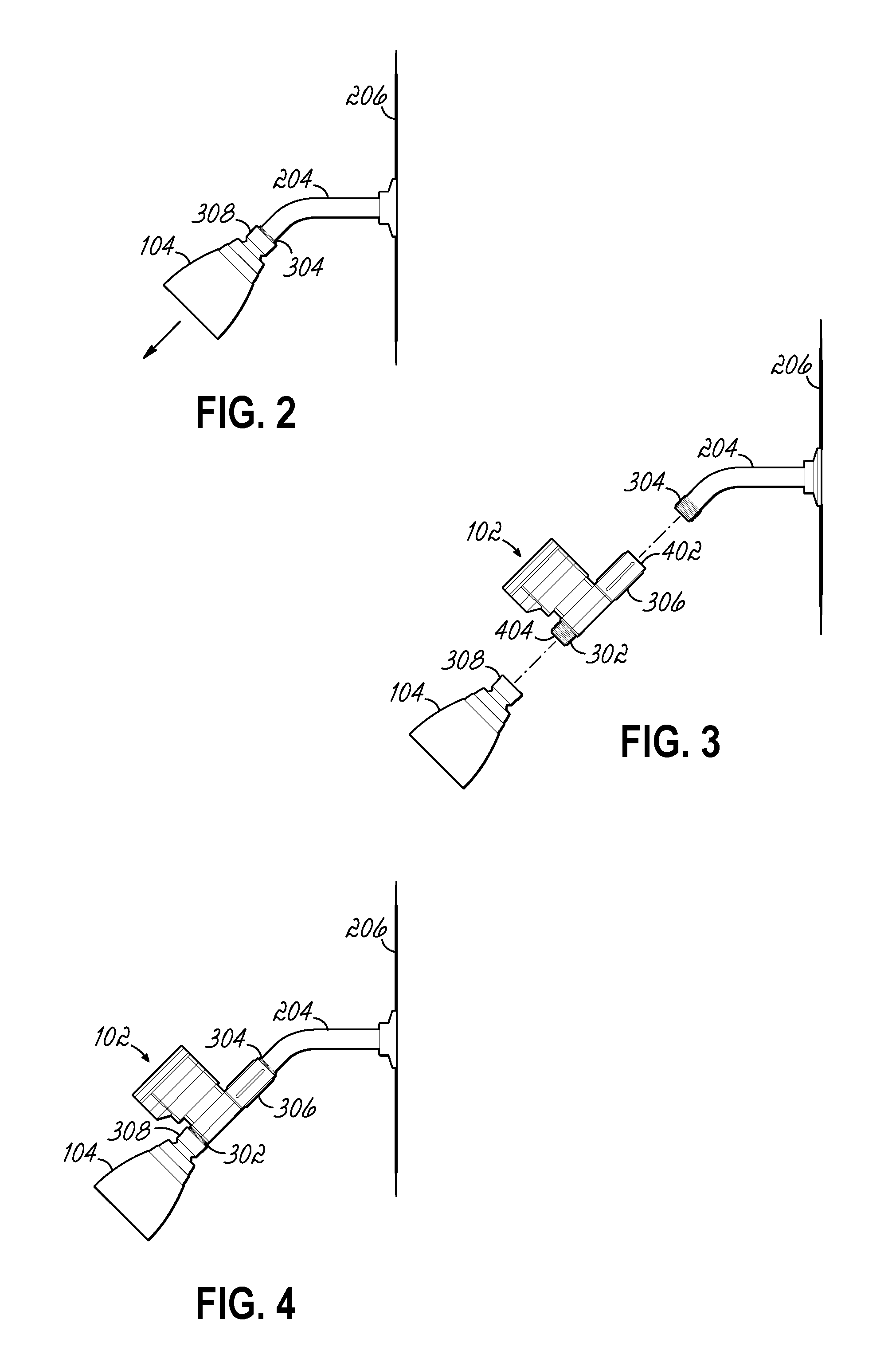
[0023]This disclosure provides systems and methods for automatically regulating water flow in a shower environment to reduce water consumption.

[0024]Reference in this specification to “one embodiment,”“an embodiment,” an “example embodiment,” etc., indicate that the embodiment described may include a particular feature, structure, or characteristic, but not every embodiment may necessarily include the particular feature, structure, or characteristic. Moreover, such phrases are not necessarily referring to the same embodiment. Further, when a particular feature, structure, or characteristic may be described in connection with an embodiment, it may be submitted that it may be within the knowledge of one of ordinary skill in the relevant art to affect such feature, structure, or characteristic in connection with other embodiments whether or not explicitly described.

[0025]The following detailed description refers to the accompanying drawings that illustrate exemplary embodiments. Other ...


PUM


Abstract

According to an embodiment, a showerhead for automatically regulating water flow is provided. The showerhead comprises a range sensor, a solenoid, and a microprocessor. The range sensor is configured to detect the presence or absence of a person near the showerhead and to generate a range signal. The microprocessor is configured to receive the range signal and to determine a person's typical distance from the showerhead when rinsing. Further, based on the range signal, the microprocessor is configured to send an open signal to the solenoid valve when the person is within the typical distance and to send a close signal to the solenoid valve when the person is outside of the typical distance. The solenoid valve is configured to be opened and closed by the respective open or close signals to respectively turn on or off the flow of water based on the person's position relative to the showerhead.

Description

CROSS REFERENCE TO RELATED APPLICATION[0001]Pursuant to 37 C.F.R. §1.78(a)(4), this application claims the benefit of and priority to prior filed co-pending Provisional Application Ser. No. 62 / 189,245 filed Jul. 7, 2015, which is expressly incorporated herein by reference.FIELD OF THE INVENTION[0002]This invention relates generally to a showerhead for regulating water flow, and more particularly to a showerhead that is automated and provides a water-saving functionality.BACKGROUND OF THE INVENTION[0003]Showering is an important part of the regular routine of many individuals throughout the world. In recent years, significant efforts have been expended to reduce the amount of water used when showering, for both cost-saving reasons and in the interest of reducing environmental impact. For example, many parts of the world suffer from drought conditions resulting in shortages of drinking water for their populations.[0004]Generally speaking, a large portion of potable water is used for s...

Claims


Application Information

Patent Timeline
Patent Type & Authority Applications(United States)
IPC IPC(8): E03C1/05B05B15/06B05B12/12B05B1/18B05B1/30
CPCE03C1/057B05B1/18F16K31/0655B05B12/124B05B15/065B05B1/3013E03C1/0408B05B15/65
Inventor BURNS, STEPHEN S.
Owner BURNS STEPHEN S
Why Eureka
Try Eureka