Double diaphragm pump

Active Publication Date: 2017-01-12
WAGNER INT
View PDF6 Cites 1 Cited by
  • Summary
  • Abstract
  • Description
  • Claims
  • Application Information

AI Technical Summary

Benefits of technology

The double diaphragm pump described in this patent has several technical effects. Firstly, it includes a driving means that can move a piston or a diaphragm in at least one direction, which improves the efficiency and accuracy of the pump. Secondly, the diaphragms are mechanically prestressed before the supply phase, which further optimizes the pressure curve and allows for a fine adjustment. Additionally, the pump includes a reversing valve and a control valve that prevents any unintentional stopping of the pump. Finally, the end position switches enable the detection of the end positions of the pistons or diaphragms, ensuring that they complete the entire stroke.

Problems solved by technology

As a result, it is not possible to add the B component at any time.

Method used


Image

  • Double diaphragm pump
  • Double diaphragm pump
  • Double diaphragm pump

Examples


Embodiment Construction

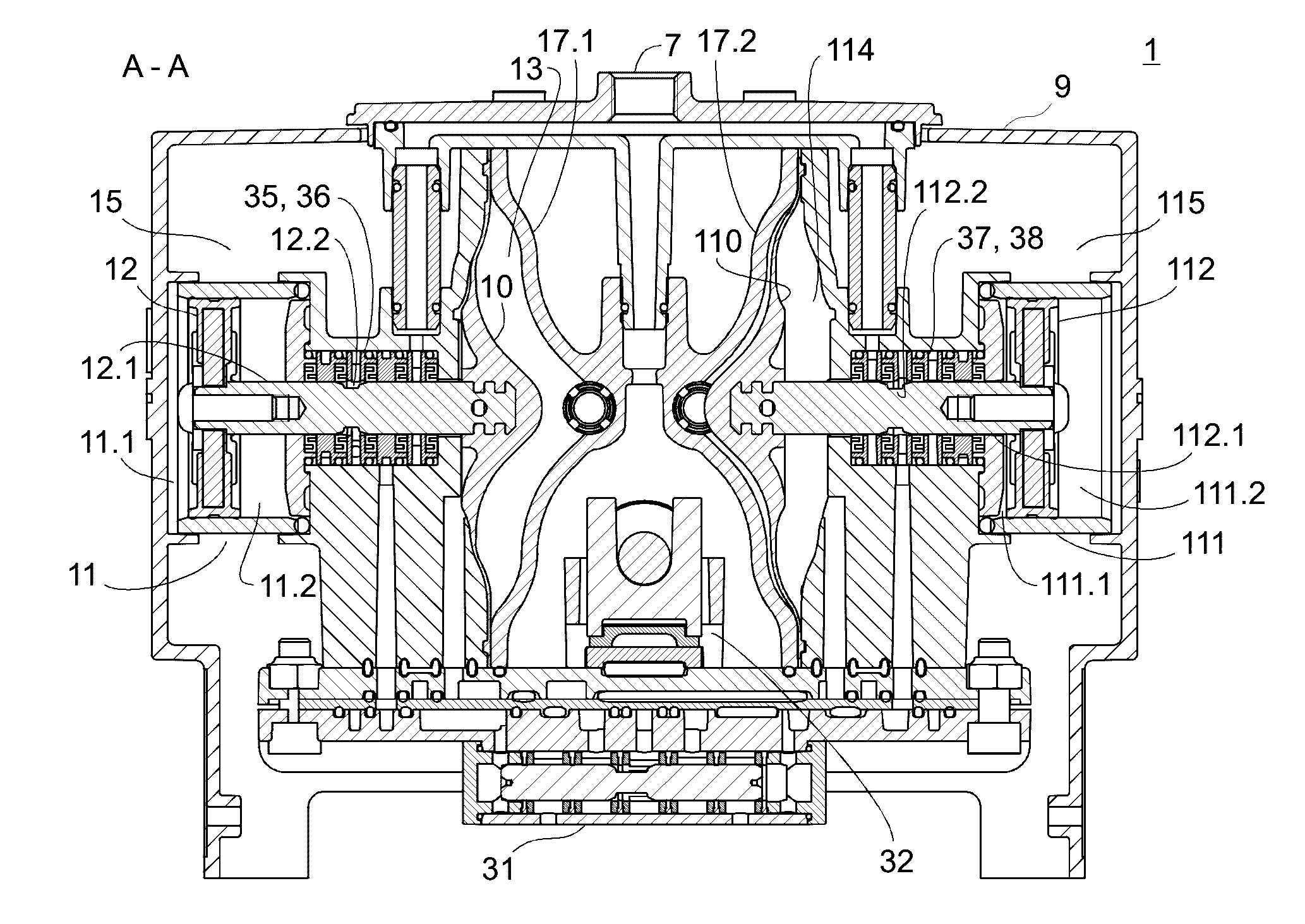
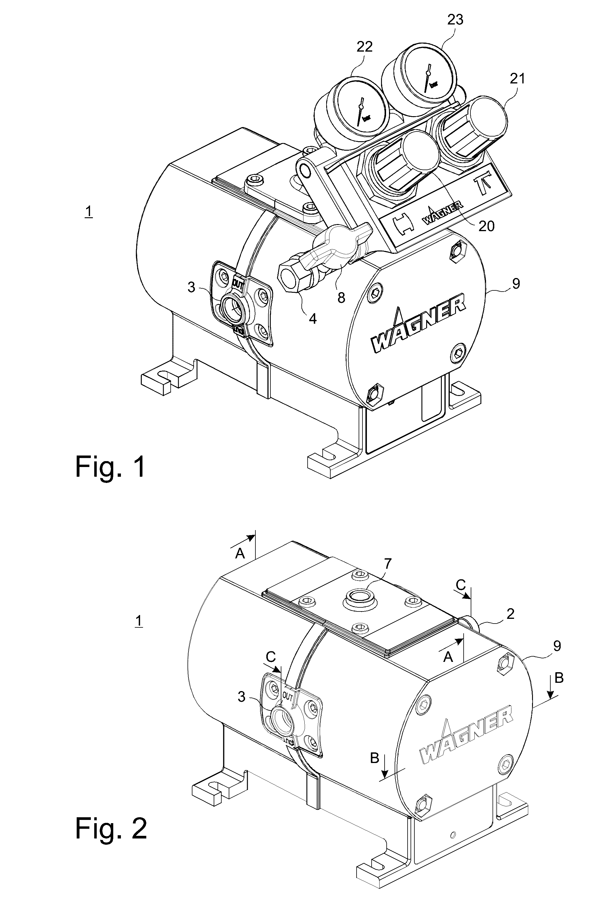
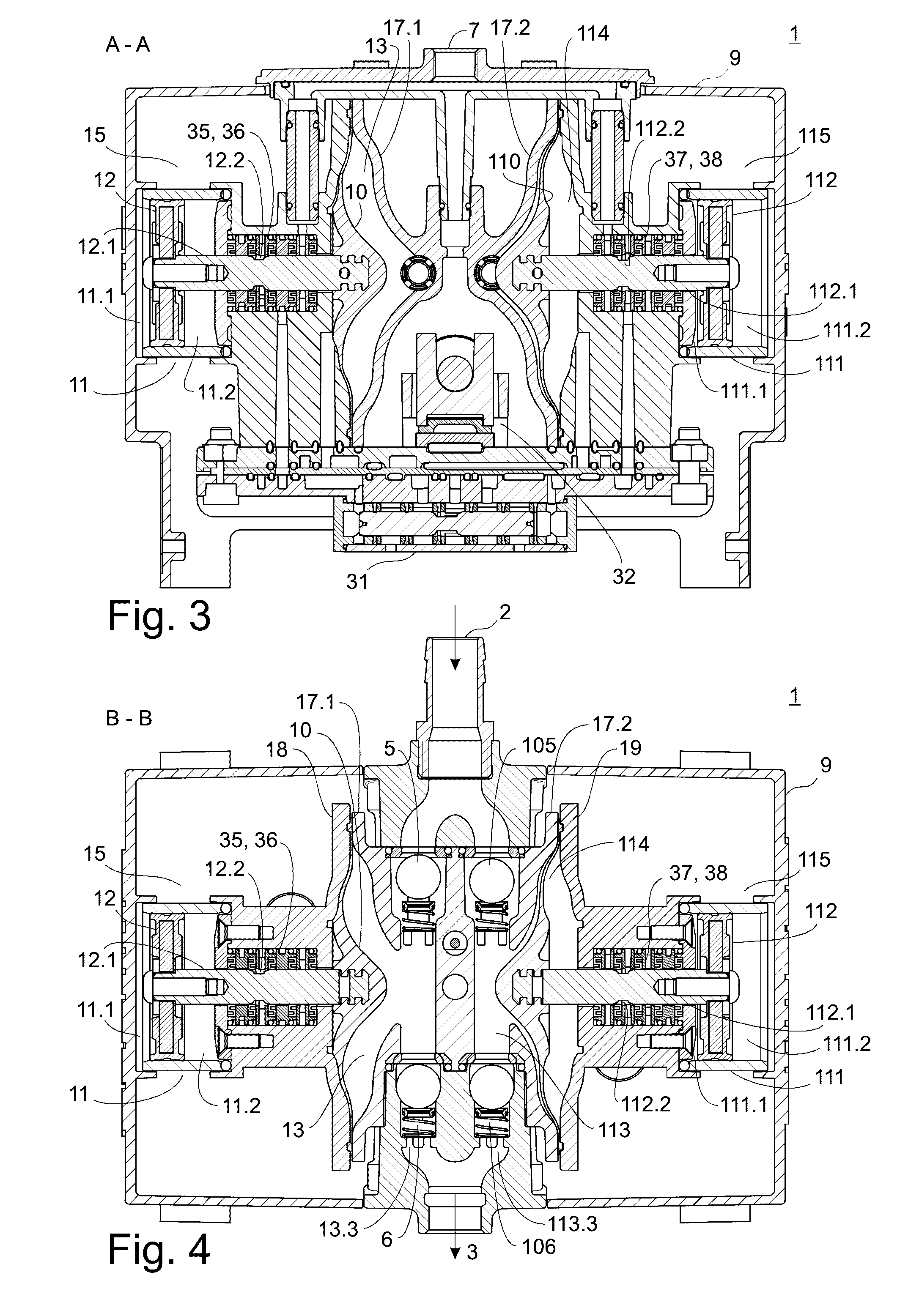
[0047]FIGS. 1 and 2 are three-dimensional views of a first potential embodiment of the double diaphragm pump 1 according to the invention. The double diaphragm pump 1 comprises a housing 9 which accommodates a first diaphragm pump and a second diaphragm pump (see FIGS. 3 and 4). An operating unit with two pressure gauges 22, 23, two pressure adjusters 20, 21, one compressed air connection 4, and one shut-off valve 8 can be arranged on the housing 9. The operating unit can be used to adjust and monitor the air pressure to supply the double diaphragm pump and the supply pressure of the double diaphragm pump. In addition, the compressed air to supply the first and second diaphragm pumps can be connected to the compressed air connection 4. FIG. 2 shows the double diaphragm pump 1 without the operating unit. A compressed air connection 7 which can be connected to the operating unit is disposed on the top of the housing 9. A pump inlet 2 for the medium to be supplied and a pump outlet 3 f...


PUM


Abstract

A first diaphragm which forms a wall of a first pump chamber is provided in the double diaphragm pump according to the invention, wherein the first diaphragm can be moved by means of a first driving means. In addition, a second diaphragm which forms a wall of a second pump chamber is provided, wherein the second diaphragm can be moved by means of a second driving means. What is more, a control for the driving means is provided, said control being designed and operable such that it controls the two driving means subject to one or a plurality of conditions.

Description

CROSS-REFERENCE TO RELATED APPLICATION[0001]The present application claims priority under 35 USC §119 to European Patent Application No. 15176316.6, filed Jul. 10, 2015, the entire disclosure of which is incorporated herein by reference.TECHNICAL FIELD[0002]The invention relates to a double diaphragm pump for the supply of fluid, such as paint or varnish.DESCRIPTION OF THE RELATED ART[0003]The publication DE 38 76 169 T2 discloses a known double diaphragm pump. This pump comprises a first pump chamber and a second pump chamber as well as a first pressure chamber and a second pressure chamber, wherein the first pump chamber and the first pressure chamber are separated from each other by a first diaphragm and the second pump chamber and the second pressure chamber are separated from each other by a second diaphragm. The two diaphragms are mechanically connected by means of a shaft. The shaft extends axially along an axis through the center point of each of the diaphragms and is mounte...

Claims


Application Information

Patent Timeline
IPC IPC(8): F04B43/073F04B53/14F04B9/137F04B53/10F04B49/22F04B53/16
CPCF04B43/0736F04B49/22F04B53/16F04B9/137F04B2203/10F04B53/14F04B2205/05F04B2201/0201F04B53/1015F04B43/0081F04B43/06F04B43/067F04B45/043F04B45/047F04B45/053
Inventor LUTZ, GILBERTJUTERBOCK, KARSTENBASSO, ANGELOKLUSER, THOMAS
Owner WAGNER INT
Why Eureka
Try Eureka