Wave Speed Reducer Having Self-locking Function And Compound Type Reducer Device

a speed reducer and self-locking technology, which is applied in the direction of toothed gearings, belts/chains/gearrings, toothed gearings, etc., can solve the problems of inability to disclose or teach or study, and unstable speed of roller moving into the next spline aperture. , to achieve the effect of poor driving accuracy

Inactive Publication Date: 2017-01-12
PRODRIVES & MOTIONS +1
View PDF0 Cites 7 Cited by
  • Summary
  • Abstract
  • Description
  • Claims
  • Application Information

AI Technical Summary

Benefits of technology

[0013]The objective of the present invention is to solve a problem that poor driving accuracy in view of tiny rotation angle at an output end for a conventional wave-motion mechanism is improved by using a wave speed reducer. A cam of the wave speed reducer is designed self-locking is implemented when reverse transmission occurs between the cam, a roller, a bearing member and a spline aperture so as to solve the problem of no self-locking function for the conventional wave-motion mechanism.
[0023]According to the present invention, the effect and advantages are the wave speed reducer has self-locking function. In particular, when one of the bearing member and the spline wheel used as an output end carries out reverse transmission to be used as an input end, self-locking function occurs between the cam, the roller, the bearing member and the spline member via the formation of the convex arc so as to protect transmission components in the reducer mechanism from unpredictable reverse rotation and from damages and danger.
[0042]In order to achieve technical effects of the cam periphery, the spline surface contour and the spline wheel contour, under the condition of obtaining self-locking function of the wave speed reducer, the method can design a tooth flank contour in order to design a cam circumference segment of a spline wheel, and can design a cam periphery matched with the spline apertures in the spline wheel according to the ideal moving way of the rollers in the roller-type wave-motion so as to sufficiently and really transmit driving force exerted from the rollers via a tooth flank during a process of the cam surface pushing the rollers to contact tooth flank of the spline apertures. The tooth flank can be used as an effective contact surface of the cam for providing force to the rollers in order to maintain good driving accuracy and driving efficiency at a ratio of reduction of a certain output value for the roller-type wave-motion, and the driving accuracy at the output end of the roller-type wave-motion is increased.

Problems solved by technology

The well-known patents did not disclose or teach or study that the techniques of forming the contour of spline apertures and the cams were capable of effectively transmitting functional force, such as, when an input shaft rotated for half a circle, the rollers would move into a next position of the spline aperture.
During the procedures, the speed would become uncertain because of an unclear definition of the V-shape so that the speed of the roller moving into the next spline aperture would become unstable.

Method used


Image

  • Wave Speed Reducer Having Self-locking Function And Compound Type Reducer Device
  • Wave Speed Reducer Having Self-locking Function And Compound Type Reducer Device
  • Wave Speed Reducer Having Self-locking Function And Compound Type Reducer Device

Examples


Embodiment Construction

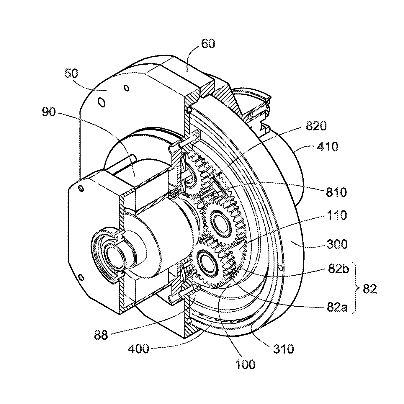
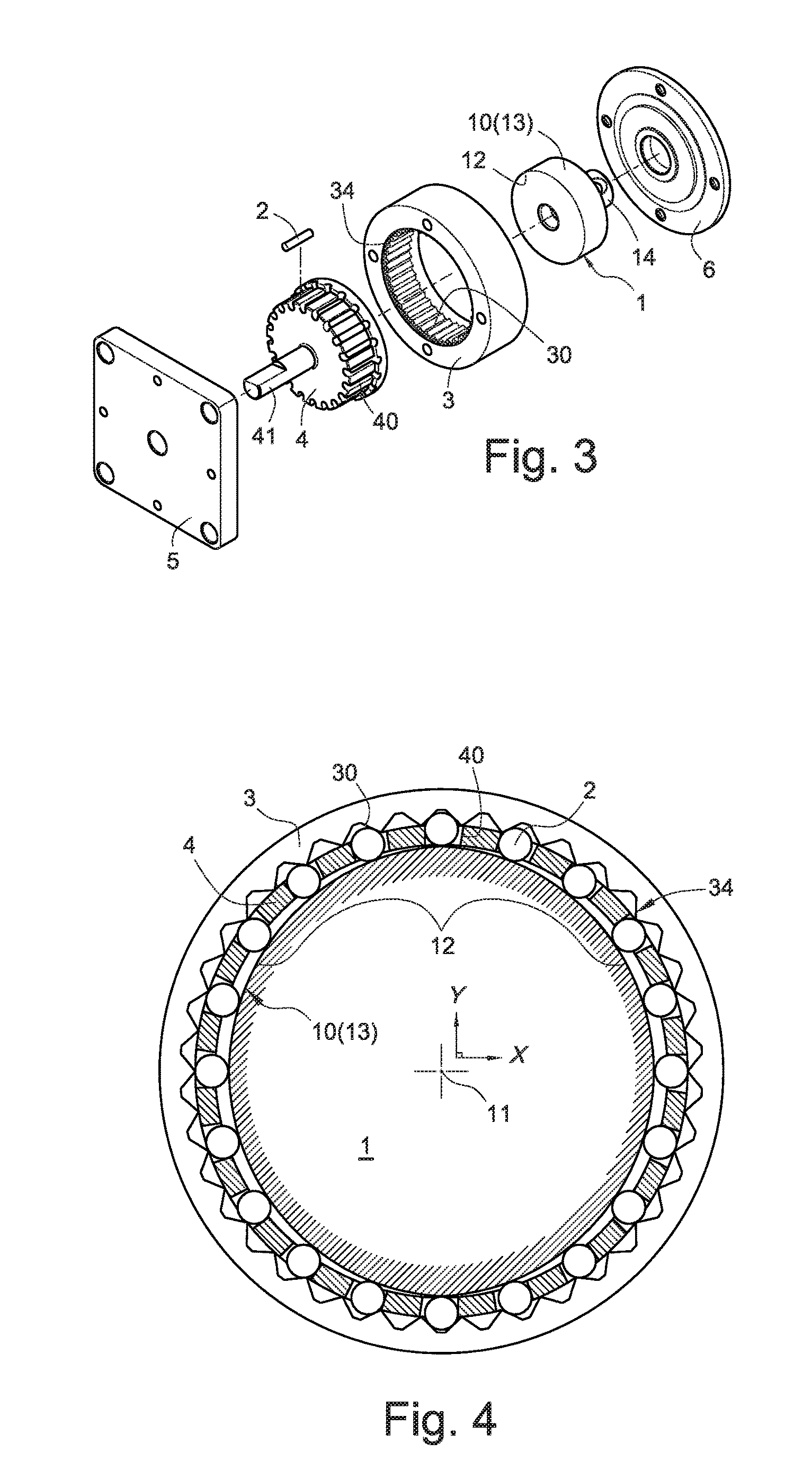
[0074]Please refer to FIGS. 3 and 4 which respectively demonstrate the members and the arrangement of the wave speed reducer designed in the present invention. A cam 1, a plurality of rollers 2, a bearing member 4 and a spline wheel 3 are arranged co-axially from inside to outside between a seat 5 and a cover 6 in the wave speed reducer. An input shaft 14 is disposed at the axial position of the cam 1 to be used as an input end of the force of the wave speed reducer. The input shaft 14 can be transmitted rotational energy to input and drive the cam 1 to rotate. A convex arc 12 in spline line shape and located relatively far from the axis 11 is disposed in a cam surface 10 of the cam 1. The convex arc 12 is used as an effective functional area for pushing and driving the roller to transmit power. A cam periphery 13 is formed on the cam 1. In a preferred embodiment of the invention, the roller 2 is in cylinder shape. But, the roller 2 might be a bearing bead used as a roller part. The...


PUM


Abstract

The invention provides a wave speed reducer having a self-locking function comprising a structure for outputting driving rotation of a bearing member or a spline wheel at a specific reduction ratio which drives rollers to rotate by a cam. A designed convex arc of the cam has self-locking function of restricting the rollers to reversely rotate so as to form a compound type reducer device having a multi-reducer function by mutually combining the wave speed reducer and a planetary gear set. To solve conventional problems, poor driving accuracy at tiny rotation angle and scarcity of self-locking function for conventional reducers are improved.

Description

BACKGROUND OF THE INVENTION[0001]1. Field of the Invention[0002]The present invention relates to a structural arrangement technique of a reducer, particularly to a speed reducer having a self-locking function and a compound type reducer device thereof.[0003]2. Description of Related Art[0004]In the structural arrangement technical field of conventional reducers, the self-locking function to be studied herein meant that driving power was loaded on an active member so as to generate forward output at a specific reduction ratio from a driven follower. When no driving power was loaded on the active member to be a free end, driving power (including a driving force exerted by an external power source, a driving force from torque generated by their gravity force of the follower and its connected members) was so loaded on the follower that it could not drive the active member of the free end to reversely rotate, i.e. the so-called “self-locking”. The “self-locking” meant a mechanism generat...

Claims


Application Information

Patent Timeline
Patent Type & Authority Applications(United States)
IPC IPC(8): F16H49/00F16H1/46
CPCF16H1/46F16H49/001F16H2049/003
Inventor LIANG, CHIA-SHENGCHENG, HUNG-TAIHUANG, SZU-MING
Owner PRODRIVES & MOTIONS
Why Eureka
Try Eureka