Housing with a damping element for a micromechanical sensor element

Active Publication Date: 2017-01-12
ROBERT BOSCH GMBH
View PDF4 Cites 4 Cited by
  • Summary
  • Abstract
  • Description
  • Claims
  • Application Information

AI Technical Summary

Benefits of technology

[0003]An object of the present invention is therefore

Problems solved by technology

The production of such housings can be technically very comp

Method used


Image

  • Housing with a damping element for a micromechanical sensor element
  • Housing with a damping element for a micromechanical sensor element
  • Housing with a damping element for a micromechanical sensor element

Examples


Embodiment Construction

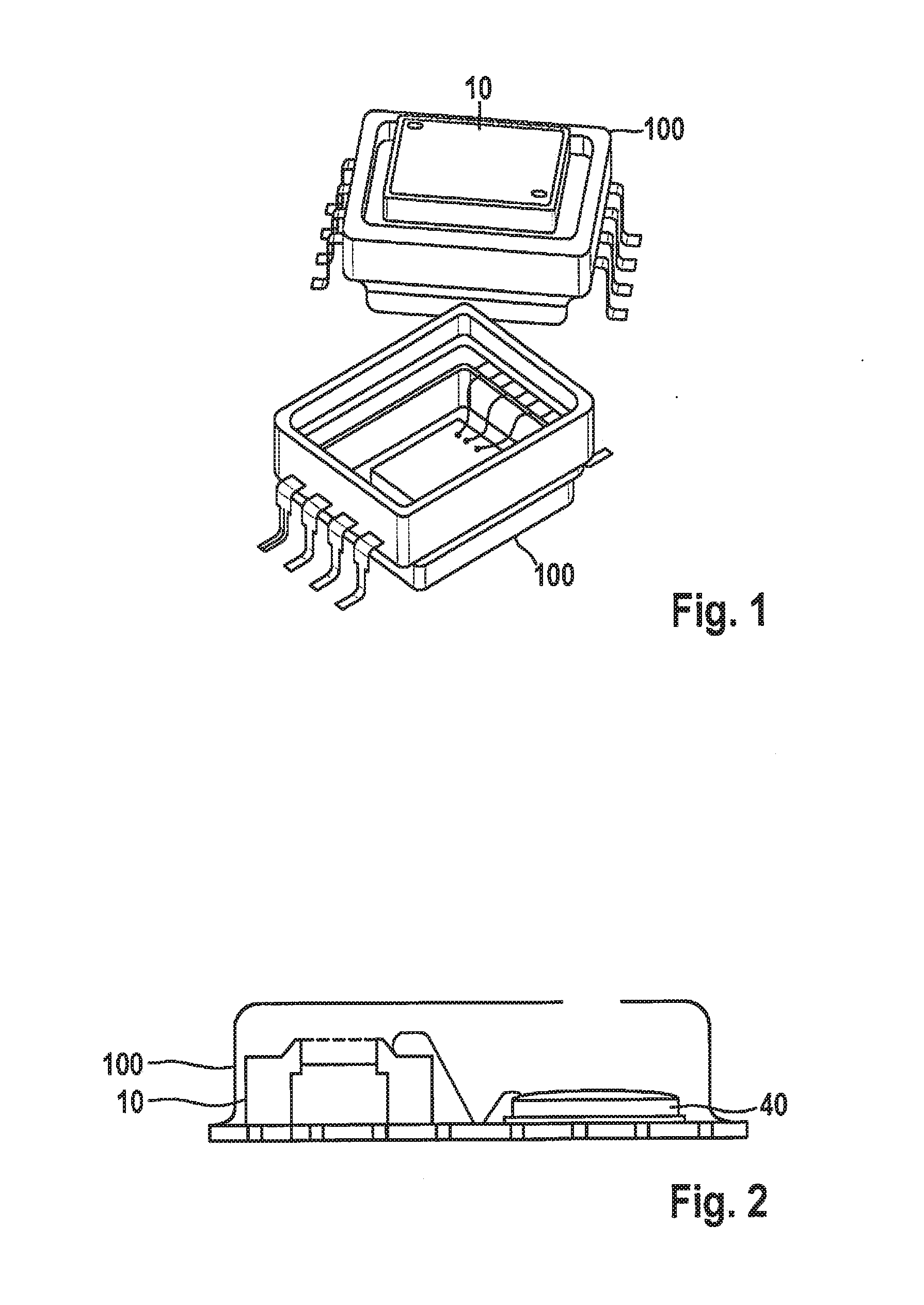
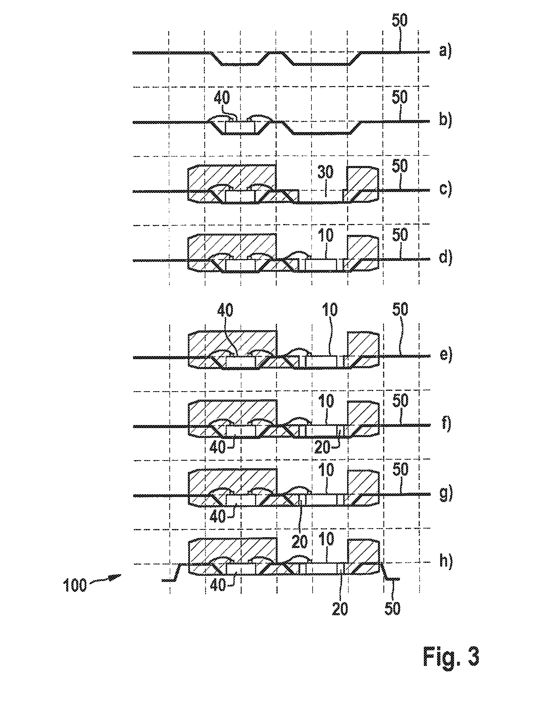
[0028]FIG. 1 shows by way of example, in two perspective views, a housing 100, embodied as a premold housing, for a pressure sensor, a micromechanical sensor element 10 being disposed inside housing 100.

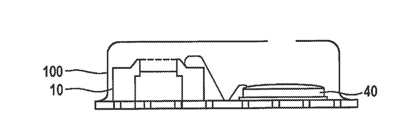
[0029]FIG. 2 shows by way of example a pressure sensor, built up on a circuit board substrate, having a micromechanical sensor element 10 and an application-specific integrated circuit (ASIC) 40. An opening on the upper side of housing 100, provided for media equalization, is evident.

[0030]Housings 100 of FIGS. 1 and 2 are used, for example, for acceleration sensors and rotation rate sensors. The latter have, as a result of the drive concept, an oscillator structure that oscillates at the drive frequency fA. Detection occurs in phase-shifted fashion, also at that frequency fA. If housing 100 of the sensor has an eigenmode in the region of the drive frequency fA, signal delivery then disadvantageously occurs when the external stimulus is not present. This problem is especially critica...


PUM

PropertyMeasurementUnit
Massaaaaaaaaaa
Frequencyaaaaaaaaaa
Elasticityaaaaaaaaaa

Abstract

A housing for a micromechanical sensor element, including a cavity in which the sensor element is disposable, and a damping element, the micromechanical sensor element being immobilizable in the cavity by the damping element so that the damping element and the sensor element together have a substantially common center of mass.

Description

FIELD OF THE INVENTION[0001]The present invention relates to a housing for a micromechanical sensor element. The invention further relates to a method for manufacturing a sensor device.BACKGROUND INFORMATION[0002]Sensor modules that require access to a medium (e.g. air, water, fluid, etc.), for example pressure sensors, are typically packaged in so-called “premold” housings or built up on a circuit board substrate, and capped with a cover made, for example, of steel or plastic. The production of such housings can be technically very complex, and thus very expensive in small production quantities.SUMMARY OF THE INVENTION[0003]An object of the present invention is therefore to furnish an improved housing for a sensor element.[0004]The object may be achieved according to a first aspect with a housing for a micromechanical sensor element having:[0005]a cavity in which the sensor element is disposable; and[0006]a damping element, the micromechanical sensor element being immobilizable in ...

Claims


Application Information

Patent Timeline
IPC IPC(8): G01D11/24B81C1/00B81B7/00
CPCG01D11/245B81B2201/0264B81C1/00325B81B7/0058B81B2207/012
Inventor HANSEN, UWE
Owner ROBERT BOSCH GMBH
Why Eureka
Try Eureka