
Atmospheric Channel Characterization System and Method Using Target Image Information

a technology of atmospheric channel and image information, applied in the field of atmospheric channel characterization system and target image information, can solve the problems of insufficiently solving the problem of rapid and accurate spatial and temporal characterization of atmospheric conditions affecting the performance of electro-optical systems such as directed energy systems, imaging systems, and communications links

Active Publication Date: 2017-01-12
THE UNITED STATES OF AMERICA AS REPRESENTED BY THE SECRETARY OF THE NAVY
View PDF2 Cites 19 Cited by
  • Summary
  • Abstract
  • Description
  • Claims
  • Application Information

AI Technical Summary

Benefits of technology

The patent text describes an invention that aims to quickly and accurately characterize the atmosphere that affects the performance of electro-optical systems such as directed-energy systems and imaging systems. The invention is a system and method using target image information to analyze the turbulence and extinction-degraded imaging caused by atmospheric conditions. The technical effects of this invention include improved spatial and temporal characterization of atmospheric conditions, better analysis of turbulence and extinction-degraded imaging, and improved processing of target image information.

Problems solved by technology

The capability to rapidly and accurately spatially and temporally characterize atmospheric conditions affecting the performance of electro-optical systems such as directed-energy systems, imaging systems, and communications links remains an inadequately solved problem.

Method used


Image

  • Atmospheric Channel Characterization System and Method Using Target Image Information
  • Atmospheric Channel Characterization System and Method Using Target Image Information
  • Atmospheric Channel Characterization System and Method Using Target Image Information

Examples


Embodiment Construction

[0010]Reference in the specification to “one embodiment” or to “an embodiment” means that a particular element, feature, structure, or characteristic described in connection with the embodiments is included in at least one embodiment. The appearances of the phrases “in one embodiment”, “in some embodiments”, and “in other embodiments” in various places in the specification are not necessarily all referring to the same embodiment or the same set of embodiments.

[0011]Some embodiments may be described using the expression “coupled” and “connected” along with their derivatives. For example, some embodiments may be described using the term “coupled” to indicate that two or more elements are in direct physical or electrical contact. The term “coupled,” however, may also mean that two or more elements are not in direct contact with each other, but yet still co-operate or interact with each other. The embodiments are not limited in this context.

[0012]As used herein, the terms “comprises,”“c...


PUM


Abstract

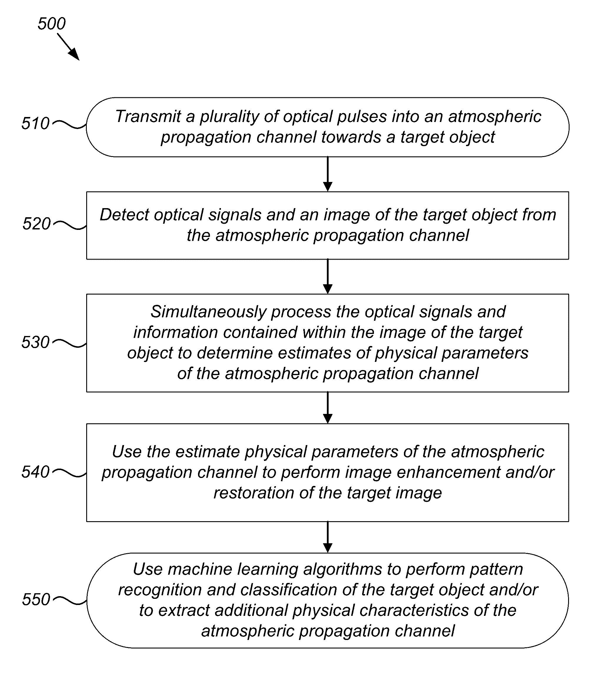
A system and method involve transmitting, using an optical device, a plurality of optical pulses into an atmospheric propagation channel towards a target object. Using an imaging device, more than one optical signals and an image of the target object are detected from the atmospheric propagation channel. The optical signals are produced by interaction between the transmitted optical pulses and the atmospheric propagation channel and include elastic backscatter return signals, inelastic backscatter return signals, and polarization signals. A processor simultaneously processes the elastic and inelastic backscatter return signals, the polarization signals, and information contained within the image of the target to determine estimates of one or more physical parameters of the atmospheric propagation channel. The processor uses machine learning algorithms to enhance / restore the image of the target, to perform pattern-recognition and classification of the target, and to extract additional atmospheric propagation channel physical characteristics.

Description

CROSS-REFERENCE TO RELATED APPLICATIONS[0001]This application claims the benefit of U.S. Provisional Patent Application Ser. No. 62 / 189,082 filed Jul. 6, 2015, entitled “Range-Gated Intensified CCD Imager for Single-Ended Atmospheric Characterization”, and U.S. Provisional Patent Application Ser. No. 62 / 189,041 filed Jul. 6, 2015, entitled “Machine Learning Method for the Analysis of Turbulence- and Extinction-Degraded Imagery”, the content of both of which being fully incorporated by reference herein.FEDERALLY SPONSORED RESEARCH AND DEVELOPMENT[0002]This invention is assigned to the United States Government. Licensing inquiries may be directed to Office of Research and Technical Applications, Space and Naval Warfare Systems Center, Pacific, Code 72120, San Diego, Calif., 92152; telephone (619) 553-5118; email: ssc_pac_t2@navy.mil. Reference Navy Case No. 103398.BACKGROUND OF THE INVENTION[0003]The capability to rapidly and accurately spatially and temporally characterize atmospheri...

Claims


Application Information

Patent Timeline
IPC IPC(8): G06T7/00G06T5/00G01N15/14G01N21/49G01N21/21G01S17/18G01S17/89
CPCG06T7/0002G01N21/49G01N21/21G01N15/1429G06T2207/30192G06T2207/20081G06T2207/20084G06T2207/20172G06T5/001G01N21/53G01N21/65G01N2021/1793G01N2021/4709G01N2201/0697G01N2015/0046G01N2015/0026G01N15/0205G01S17/89G01S17/95G01S7/4815G01S7/4816G01S7/497G01S7/499G01S17/18Y02A90/10G06T5/60G06T5/00
Inventor REINHARDT, COLIN N.
Owner THE UNITED STATES OF AMERICA AS REPRESENTED BY THE SECRETARY OF THE NAVY
Learn More