High-energy laser atmospheric compensation and aimpoint maintenance

a high-energy laser and atmospheric compensation technology, applied in the direction of laser details, instruments, measurement devices, etc., can solve the problems of beacon illuminator increasing the complexity, power draw, and weight of the overall weapon system, and prohibiting the reference to each other

Inactive Publication Date: 2012-07-10
THE GOVERNMENT OF THE UNITED STATES AS REPRESENTED BY THE UNITED STATES AIR FORCE
View PDF1 Cites 29 Cited by
  • Summary
  • Abstract
  • Description
  • Claims
  • Application Information

AI Technical Summary

Benefits of technology

[0008]High-energy laser weapon systems normally need to compensate for atmospheric fluctuations using adaptive optics. The atmospheric compensation is usually done using a separate beacon illuminator laser to create a pseudo star on the target and sense the return in a wavefront sensor to drive the adaptive optics. In the present invention the high-energy laser itself is used as a beacon illuminator by turning it off periodically for a very short period giving the wavefront sensor and aim point sensor an opportunity to measure the return from the high-energy laser. In addition, the high-energy laser weapon can be snapped ahead of the path of the target to avoid anisoplanatism.

Problems solved by technology

For size, weight, and complexity limitations, the HEL and BIL systems are usually shared aperture designs that both transmit the high-energy laser and sense the target through the same telescope since building a second separate telescope and referencing the two to each other tends to be prohibitive.
The other reason is the fact that the BIL is an unresolved point on the target and is subject to the range squared loss.
A beacon illuminator increases the complexity, power draw, and weight of the overall weapon system.
Examples of these limitations are the Airborne Laser with its kilowatt class beacon illuminators, complex optical system, high weight and large volume.
Another example is the Advanced Tactical Laser that has no beacon illuminator due to the size and weight limitations of the small aircraft platform upon which it is mounted.
Consequently, it cannot compensate for atmospheric turbulence resulting in greatly increased time on target to be effective.

Method used


Image

  • High-energy laser atmospheric compensation and aimpoint maintenance
  • High-energy laser atmospheric compensation and aimpoint maintenance
  • High-energy laser atmospheric compensation and aimpoint maintenance

Examples


Embodiment Construction

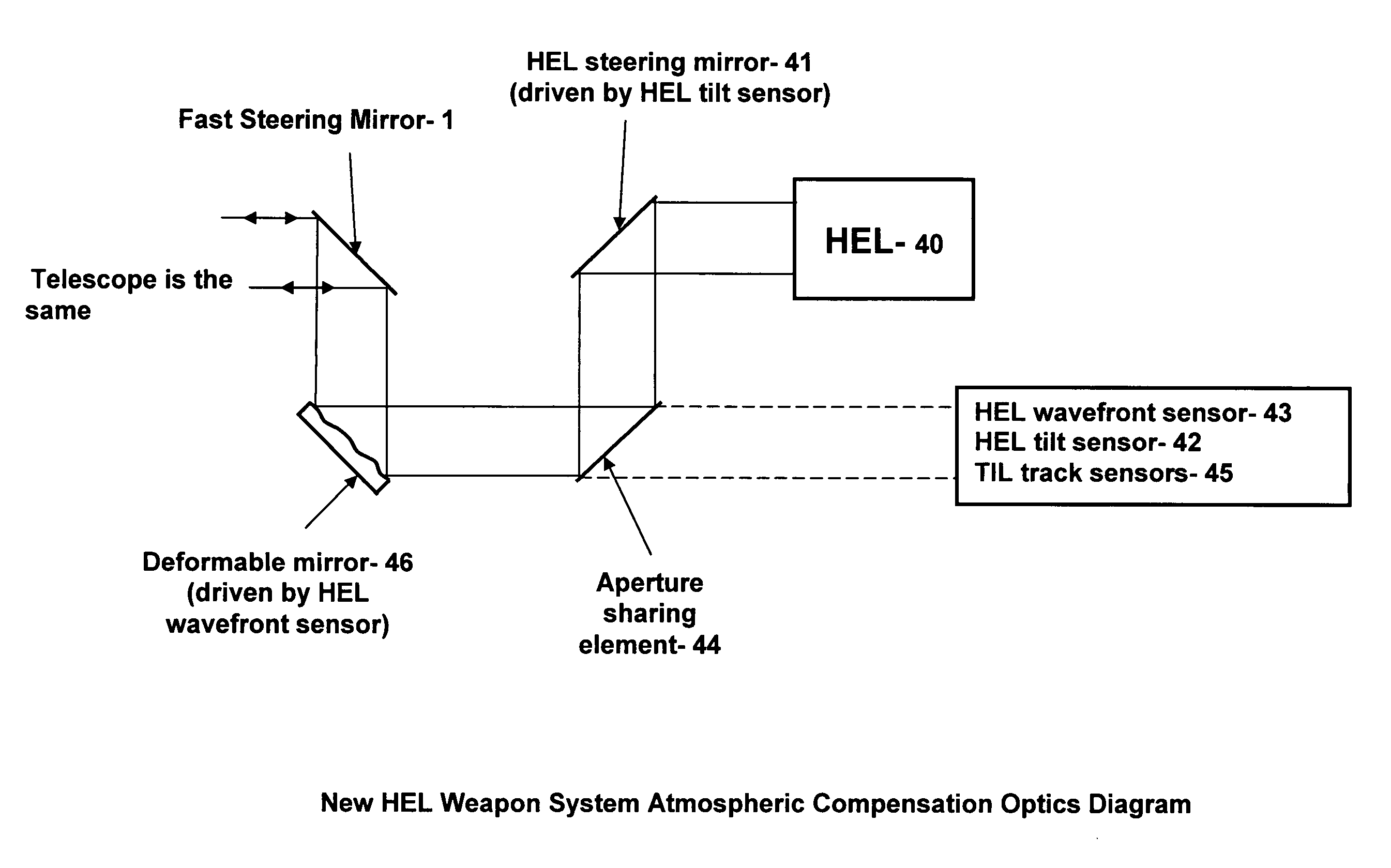
[0014]The present invention uses the high-energy laser itself to measure the atmospheric disturbances and the location of the laser on the target by turning the high-energy laser off for a very brief time (negative pulse), for example 200 nanoseconds to 20 microseconds, while the wavefront sensor and aim point sensor look at the high-energy laser return. The wavefront sensor is not operated for the first approximate 100 ns of the negative pulse to give the outgoing photons and any backscatter a chance to clear the local optics and very close atmosphere just outside the output telescope. The photons travel at about one foot per nanosecond and, therefore, about 50 feet of beam train is clear of outgoing high-energy laser light in the first 100 ns (round trip of 100 ft). Since the return from the target is very strong due to the high power of the high-energy laser, there are plenty of photons to detect in the short wavefront sensor integration time of 0.100 to 1.9 microseconds or whate...


PUM


Abstract

A high-energy laser weapon system in which the high-energy laser beam itself is used to correct for atmospheric fluctuations thereby replacing a separate beacon illuminator system. The high-energy laser is turned off (negative pulse) periodically for a very short period giving a wavefront sensor an opportunity to measure the return of the high-energy laser beam from the target. A wavefront sensor drives a deformable mirror based on this return signal avoiding wavelength anisoplanatism. In addition, the high-energy laser weapon can be snapped ahead of the path of the target during the negative pulse to avoid tilt anisoplanitism.

Description

STATEMENT OF GOVERNMENT INTEREST[0001]The conditions under which this invention was made are such as to entitle the Government of the United States under paragraph I(a) of Executive Order 10096, as represented by the Secretary of the Air Force, to the entire right, title and interest therein, including foreign rights.BACKGROUND OF THE INVENTION[0002]The present invention relates generally to atmospheric compensation and aim point maintenance for high-energy laser (HEL) weapon systems operated in the atmosphere, and in particular relates to the use of the high-energy laser itself for measuring atmospheric turbulence and for maintaining the HEL aim point.[0003]In a high-energy laser weapon system, the laser needs to be maintained on a specific area of the target for a period of time to be effective. Atmospheric compensation using adaptive optics significantly reduces the time the high-energy laser must be maintained on the target. FIG. 1 illustrates the traditional HEL engagement geom...

Claims


Application Information

Patent Timeline
Patent Type & Authority Patents(United States)
IPC IPC(8): H01S3/00
CPCF41H13/0062G01S17/66
Inventor SAUNDERS, PATRICK
Owner THE GOVERNMENT OF THE UNITED STATES AS REPRESENTED BY THE UNITED STATES AIR FORCE
Why Eureka
Try Eureka