Display device driver

a technology for display devices and drivers, applied in the direction of instruments, static indicating devices, etc., can solve the problem of varying the delay time of the delay circui

Active Publication Date: 2017-01-12
LAPIS SEMICON CO LTD
View PDF9 Cites 13 Cited by
  • Summary
  • Abstract
  • Description
  • Claims
  • Application Information

AI Technical Summary

Benefits of technology

[0013]Therefore, according to the present invention, it becomes possible to display a favorable image free from uneven color in accordance with manufacturing variations, screen sizes, or various specifications of display devices.

Problems solved by technology

However, the delay time of the delay circuit varies in dependence on manufacturing variations or the like.

Method used


Image

  • Display device driver
  • Display device driver
  • Display device driver

Examples


Embodiment Construction

[0037]Hereinbelow, an embodiment of the present invention will be described in detail with reference to the accompanying drawings.

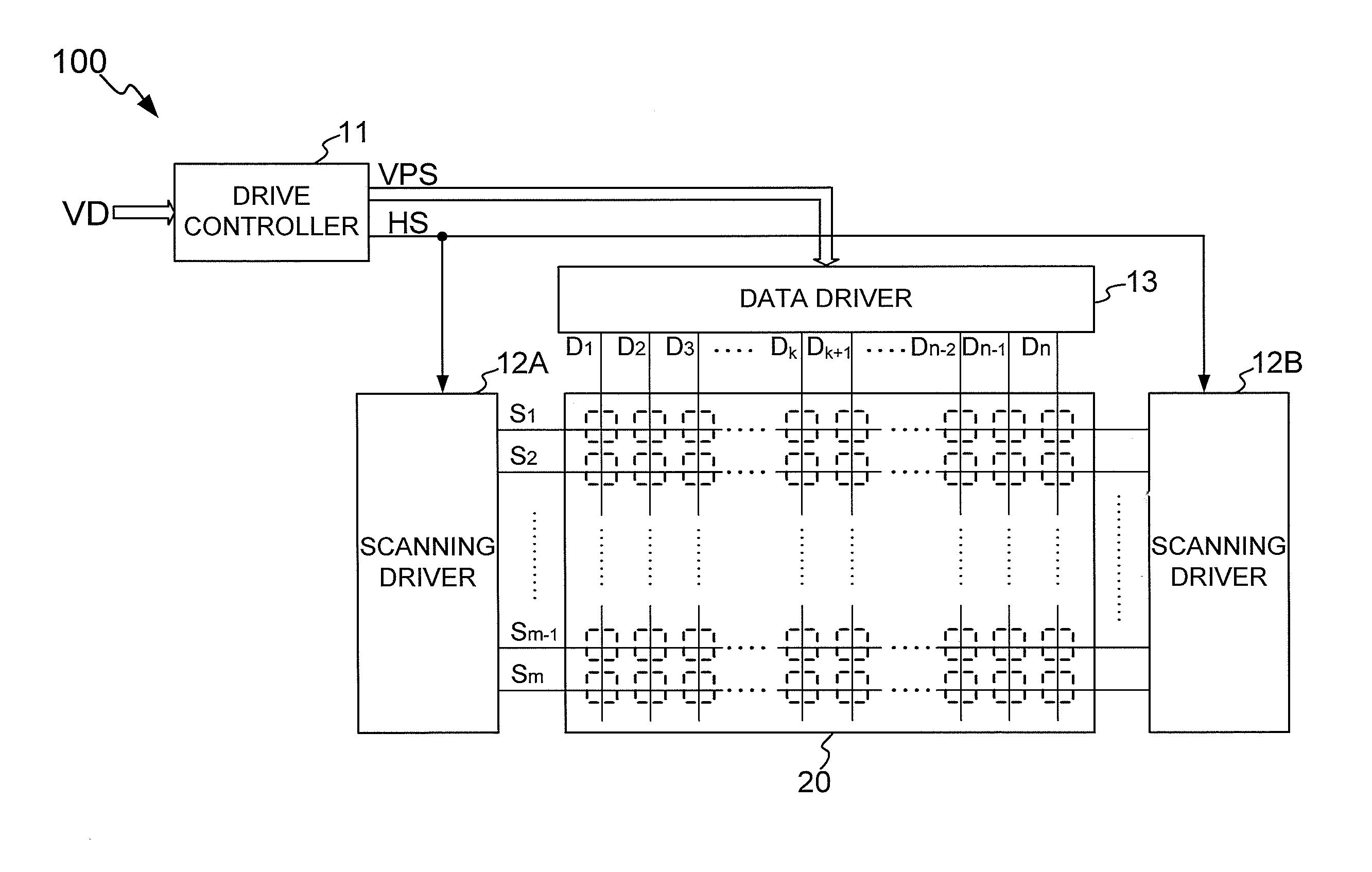
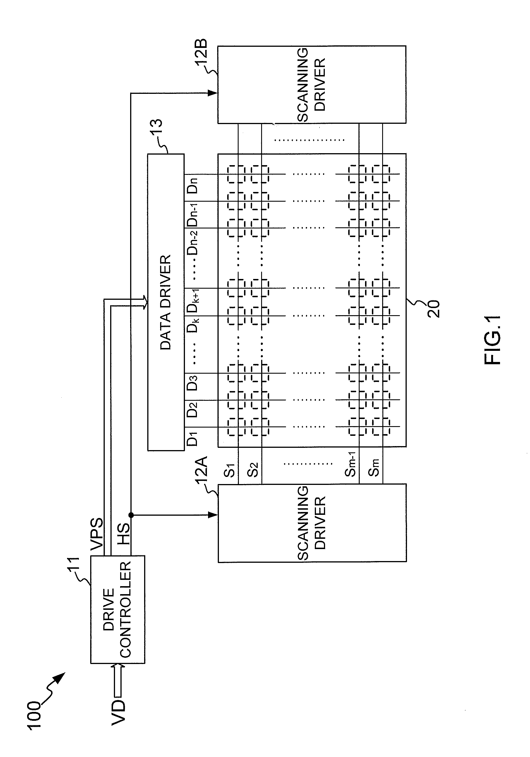
[0038]FIG. 1 is a schematic configuration view of a display apparatus 100 including a display device driver according to the present invention. In FIG. 1, the display device 20 is made of a liquid crystal or an organic EL panel, for example. The display device 20 has m (m is a natural number of 2 or more) horizontal scan lines S1 to Sm formed to extend in a horizontal direction on a two-dimensional screen and n (n is a natural number of 2 or more) data lines D1 to Dn formed to extend in a perpendicular direction on the two-dimensional screen. A display cell that serves as a pixel is formed in each crossing portion between the horizontal scan lines and the data lines.

[0039]The drive controller 11 detects a horizontal synchronization signal in a video signal VD, and supplies the horizontal synchronization signal HS to the scanning drivers 12A and 12B.

[0040]...


PUM


Abstract

A display device driver includes: a pixel drive voltage application unit; and a delay controller. The pixel drive voltage application unit converts a plurality of pixel data pieces into a plurality of pixel drive voltages, the pixel data pieces respectively representing luminance levels of respective pixels based on a video signal, the pixel drive voltages respectively having voltage values corresponding to the luminance levels, and applies the converted pixel drive voltages to the display device. The delay controller controls the pixel drive voltage application unit to apply the plurality of pixel drive voltages to the display device, the plurality of pixel drive voltages being sequentially delayed in units of groups, the groups each including t pixel drive voltages, and sets delay time designated by delay time designation signals as delay time to delay each of the pixel drive voltages.

Description

BACKGROUND OF THE INVENTION[0001]1. Field of the Invention[0002]The present invention relates to a display device driver that drives a display device in response to a video signal.[0003]2. Description of the Related Art[0004]In display devices such as liquid crystal display panels, a plurality of gate lines extending, for example, one by one in a horizontal direction on a two-dimensional screen and a plurality of source lines extending in a perpendicular direction on the two-dimensional screen are arranged so as to cross each other. The liquid crystal display panels further incorporate a source driver and a gate driver. The source driver applies a gradation display voltage to each of the source lines, the gradation display voltage corresponding to a luminance level of each pixel indicated by an input video signal. The gate driver applies a scanning signal to the gate lines.[0005]As such a source driver, there is proposed or known a device configured to individually latch a plurality...

Claims


Application Information

Patent Timeline
Patent Type & Authority Applications(United States)
IPC IPC(8): G09G3/36
CPCG09G3/3674G09G3/3696G09G2320/0223G09G3/3688G09G3/3677G09G2320/0233
Inventor HIGUCHI, KOJI
Owner LAPIS SEMICON CO LTD
Why Eureka
Try Eureka