Wire harness

a wire harness and wire technology, applied in the direction of electrical/fluid circuits, vehicle components, electrical apparatus, etc., can solve the problems of large insertion force and affecting workability, affecting the relative vibration of the conductive path or the exterior member, and affecting the conductive path or the path. , to achieve the effect of preventing the occurrence of abnormal noise, reducing the influence of the conductive path or the path, and suppressing the relative vibration of the conductive path or th

Active Publication Date: 2017-01-19
YAZAKI CORP
View PDF1 Cites 3 Cited by
  • Summary
  • Abstract
  • Description
  • Claims
  • Application Information

AI Technical Summary

Benefits of technology

[0012]The present invention has been developed in consideration of the aforementioned situation. An object thereof is to provide a wire harness capable of suppressing relative vibration of conductive paths inside an exterior member even when the exterior member has no slit.
[0014]According to the first aspect, relative vibration of the conductive path or paths in the exterior member can be suppressed due to the structure of the vibration suppression member or members. In addition, in the vibration suppression member or members, the ribs can contact the inner surface of the exterior member. Thus, a large insertion force is not required.
[0018]According to the third aspect, the tape can be wound on the vibration suppression member or members so that the vibration suppression member or members can be prevented from dropping off from the conductive path or paths. In addition, the vibration suppression member or members on which the tape is wound can be fixed to the conductive path or paths.
[0019]According to the first aspect, there is an advantage that relative vibration of the conductive path or paths in the exterior member can be suppressed even when the exterior member has no slit. Therefore, there is an advantage that not only is it possible to prevent occurrence of abnormal noise in the same manner as in the related art, but it is also possible to prevent the conductive path or paths from abutting against the inner surface of the exterior member to be thereby damaged (for example, to prevent an insulator or insulators of the conductive path or paths from being shaved or injured). That is, there is an advantage that influence on the conductive path or paths can be reduced. In addition, according to the invention, a structure based on the ribs is used. Accordingly, there is an advantage that work relating to insertion can be performed easily. Further, according to the first aspect, due to use of the exterior member having no slit, there is an advantage that moisture can be prevented from invading or an advantage that damage caused by flying stones or the like can be prevented.
[0020]According to the second aspect, the following advantage can be further obtained in addition to the advantages according to the first aspect. That is, there is an advantage that insertion performance of the vibration suppression member or members into the exterior member can be improved.
[0021]According to the third aspect, the following advantage can be further obtained in addition to the advantages according to the first or second aspect. That is, there is an advantage that the vibration suppression member or members can be prevented from dropping off from the conductive path or paths or an advantage that the vibration suppression member or members can be fixed easily.

Problems solved by technology

As a result, there may be problems as follows.
In addition, an electric wire 103 located near the slit may be damaged due to flying stones or the like even if the slit can be covered with a tape wound thereon.
However, in this case, when looseness with the exterior member increases, the vibration suppression member 104 cannot provide its original function sufficiently.
As a result, a large insertion force may be required to affect the workability.

Method used


Image

  • Wire harness
  • Wire harness
  • Wire harness

Examples


embodiment

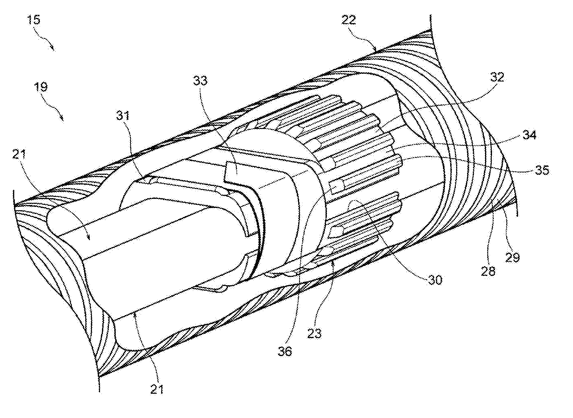
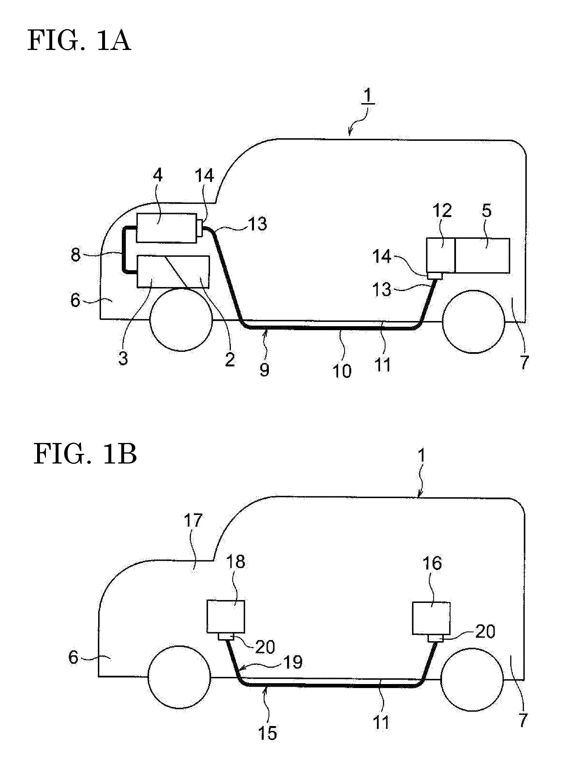
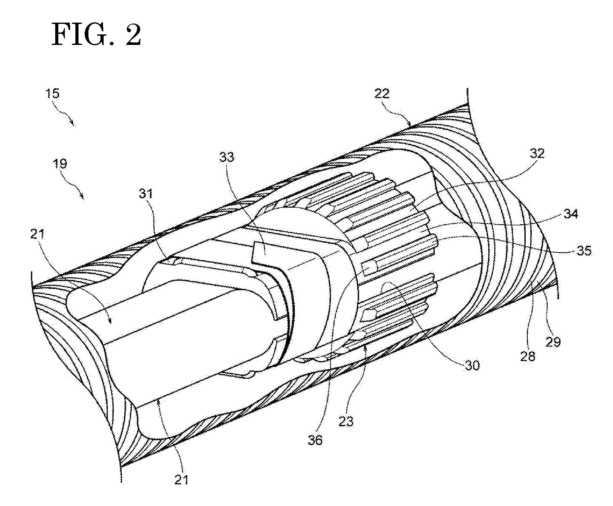
[0032]An embodiment will be described below with reference to the drawings. FIGS. 1A and 1B are views showing wire harnesses according to an embodiment of the invention. FIG. 1A is a schematic view showing a state in which high-voltage wire harnesses have been arranged. FIG. 1B is a schematic view showing a state in which a low-voltage wire harness different from those in FIG. 1A has been arranged. FIG. 2 is a perspective view showing the configuration of a harness body in a wire harness. FIG. 3 is a sectional view of the harness body in FIG. 2. FIG. 4 is a perspective view of a vibration suppression member in FIG. 2. FIG. 5 is a perspective view showing a state in which the vibration suppression member has not been attached to conductive paths yet. FIG. 6 is a perspective view showing a state in which the vibration suppression member has been attached and fixed to the conductive paths. FIG. 7 is a perspective view showing a state in which the conductive paths are being inserted int...


PUM


Abstract

A wire harness includes a tubular shaped exterior member, a conductive path protected by the exterior member, and a vibration suppression member post-fitted to the conductive path and disposed inside the exterior member. The exterior member is formed into a shape having no slit. Ribs are formed in an outer circumferential surface of the vibration suppression member so as to be disposed at circumferential intervals. The rib is formed into a shape in which a front end surface thereof in a protruding direction thereof protrudes to a position near an inner surface of the exterior member or to a position contacting the inner surface.

Description

CROSS REFERENCE TO RELATED APPLICATION[0001]This application is based on Japanese Patent Application (No. 2015-139548) filed on Jul. 13, 2015, the contents of which are incorporated herein by reference. Also, all the references cited herein are incorporated as a whole.BACKGROUND OF THE INVENTION[0002]1. Technical Field[0003]The present invention relates to a wire harness having a tubular exterior member, a conductive path or a plurality of conductive paths, and a vibration suppression member or a plurality of vibration suppression members post-fitted to the conductive path or paths and disposed inside the exterior member.[0004]2. Background Art[0005]A wire harness is used for establishing electric connection among devices mounted on a car. For example, as shown in FIG. 9, a wire harness 101 disclosed in the following Patent Literature 1 has a configuration including a corrugated tube 102 (exterior member), a plurality of electric wires 103 (conductive paths), and a vibration suppres...

Claims


Application Information

Patent Timeline
Patent Type & Authority Applications(United States)
IPC IPC(8): B60R16/02H02G3/04
CPCB60R16/0215H02G3/0481H02G3/0468H02G3/0418
Inventor YANAZAWA, KENTAKUBOSHIMA, HIDEHIKO
Owner YAZAKI CORP
Why Eureka
Try Eureka