Sensor apparatus

a technology of sensor apparatus and sensor body, which is applied in the field of sensor apparatus, can solve the problems of insufficient detection sensitivity or detection accuracy of detection parts of detection elements, such as surface acoustic wave elements, and achieve the effect of effective immobilization of components and satisfactory sensitivity or accuracy

Active Publication Date: 2017-01-19
KYOCERA CORP
View PDF1 Cites 5 Cited by
  • Summary
  • Abstract
  • Description
  • Claims
  • Application Information

AI Technical Summary

Benefits of technology

[0009]With these sensor apparatuses, the surface roughness of the immobilizing film is smaller than the surface roughness of the element electrode, or the amount of oxygen in the surface layer part of the immobilizing film is smaller than the amount of oxygen in the surface layer part of the element electrode. It is therefore possible to effectively immobilize a component (for example, a functional group, an organic member, or a biomaterial) that contributes to the detection of the detection object contained in the specimen to a surface (upper surface) of the immobilizing film. It is consequently possible to detect the detection object with satisfactory sensitivity or accuracy.

Problems solved by technology

However, the detection part of the detection element, such as the surface acoustic wave element, has failed to have sufficient detection sensitivity or detection accuracy.

Method used


Image

  • Sensor apparatus
  • Sensor apparatus
  • Sensor apparatus

Examples


first embodiment

[0027]A sensor apparatus 100 according to a first embodiment of the present invention is described with reference to FIGS. 1 to 7.

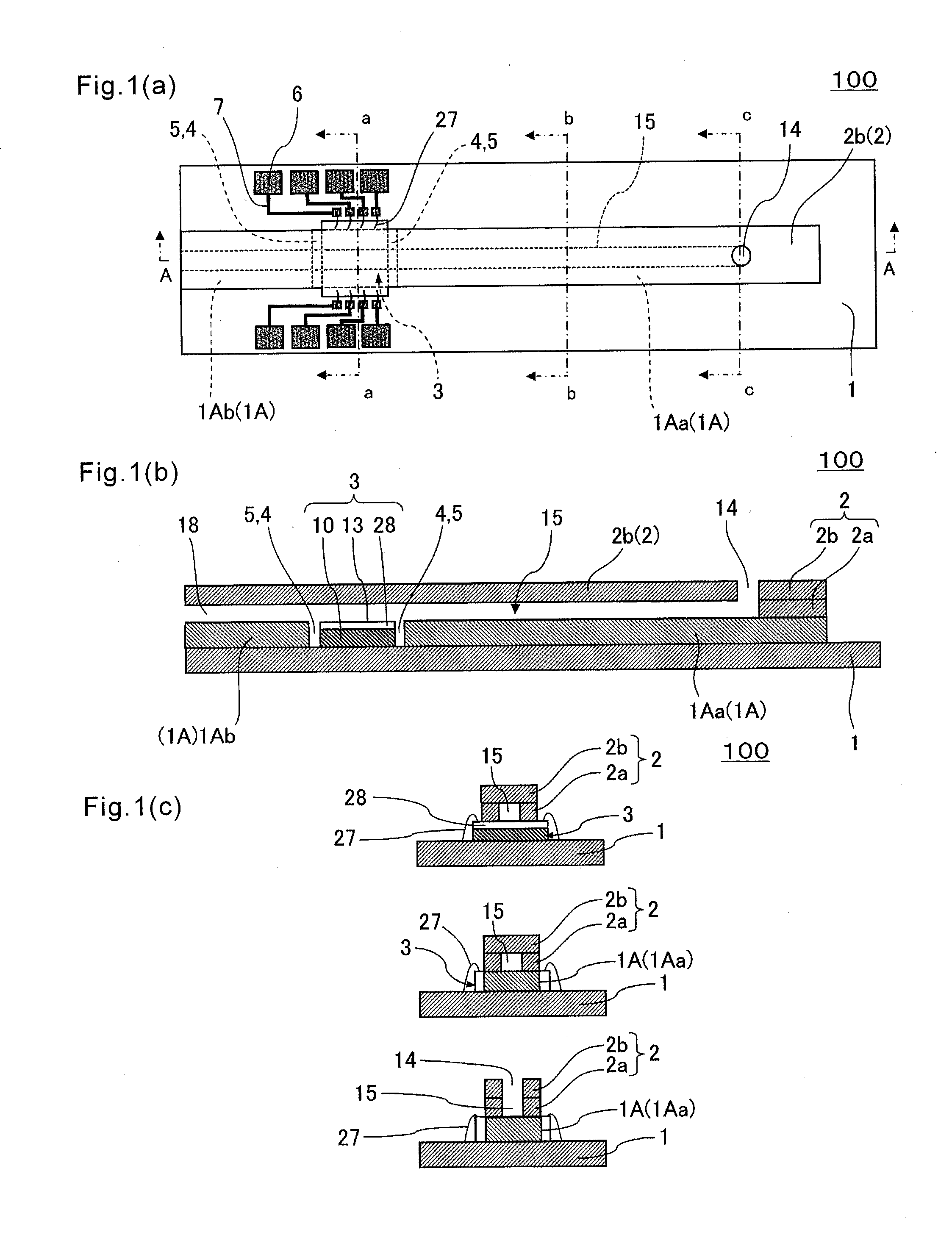
[0028]The sensor apparatus 100 of the present embodiment is mainly made up of a first cover member 1, and an intermediate cover member 1A, a second cover member 2, and a detection element 3 as shown in FIG. 1.

[0029]Specifically, as shown in FIG. 1(b), the sensor apparatus 100 includes an inlet 14 that permits entrance of a specimen liquid, and a flow channel 15 that is continuous with the inlet 14 and extends to at least a detection part 13 while being surrounded by the intermediate cover member 1A and the second cover member 2. The inlet 14 is located on an upper surface of the intermediate cover member 1A and on a side surface of the second cover member 2 as shown in FIG. 1(b). Alternatively, the inlet 14 may penetrate the second cover member 2 in a thickness direction thereof as shown in FIG. 16(b).

[0030]In the sensor apparatus 100 of the present embod...

second embodiment

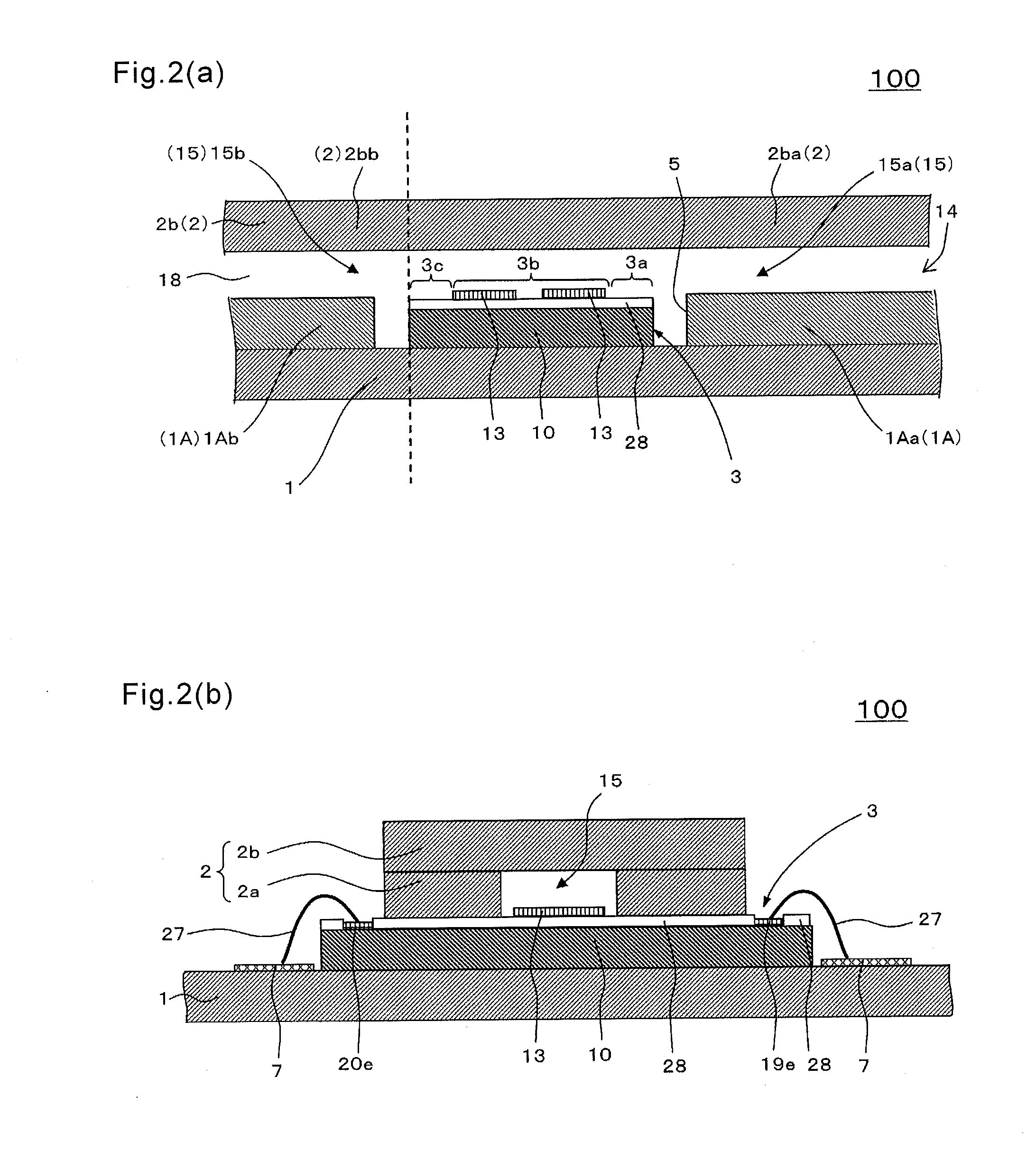
[0149]FIG. 13 is a diagram showing a sensor apparatus 200 according to a second embodiment of the present invention, and corresponds to FIG. 2(a).

[0150]In the sensor apparatus 200 of the present embodiment, a liquid absorbing material 30 that absorbs a specimen liquid at a predetermined speed is disposed at a terminal portion of the flow channel 15 on the upper surface of the first downstream portion 1Ab of the intermediate cover member 1A. Therefore, by absorbing an excessive specimen liquid, the amount of the specimen liquid flowing on the detection part 13 can be made constant to achieve highly stable measurement. As the liquid absorbing material 30, a porous material capable of absorbing liquid, such as a sponge, is usable. It is preferable to use, for example, nitrocellulose.

[0151]Also in the sensor apparatus 200 of the present embodiment, the detection element 3 and the intermediate cover member 1A that constitutes at least a part of the flow channel 15 are disposed together a...


PUM

PropertyMeasurementUnit
lengthaaaaaaaaaa
lengthaaaaaaaaaa
diameteraaaaaaaaaa

Abstract

A sensor apparatus according to an embodiment of the present invention includes an element substrate, an element electrode located on an upper surface of the element substrate, an insulating member covering at least a part of the element electrode, and a detection part that includes an immobilizing film located on the upper surface of the element substrate or an upper surface of the insulating member, and performs a detection of a detection object contained in a specimen. A surface roughness of the immobilizing film is smaller than a surface roughness of the element electrode. In a sensor apparatus of other embodiment of the present invention, an amount of oxygen in a surface layer part of the immobilizing film is smaller than an amount of oxygen in a surface layer part of the element electrode.

Description

TECHNICAL FIELD[0001]The present invention relates to a sensor apparatus capable of measuring nature of a specimen or ingredients contained in the specimen.BACKGROUND ART[0002]A sensor apparatus has been known which measures nature or ingredients of a specimen by using a detection element, such as a surface acoustic wave element (for example, refer to Japanese Unexamined Patent Publication No. 5-240762).[0003]For example, the sensor apparatus using the surface acoustic wave element has, on a piezoelectric substrate, a detection part to be reacted with ingredients contained in a specimen. The sensor apparatus is configured to detect the nature or ingredients of the specimen by measuring a change of a surface acoustic wave after propagating along the detection part.SUMMARY OF THE INVENTION[0004]However, the detection part of the detection element, such as the surface acoustic wave element, has failed to have sufficient detection sensitivity or detection accuracy.[0005]Hence, there has...

Claims


Application Information

Patent Timeline
Patent Type & Authority Applications(United States)
IPC IPC(8): G01N29/02
CPCG01N29/022G01N2291/022G01N2291/0256G01N2291/0423G01N2291/0255B01L3/5027B01L2300/0645B01L2300/0663B01L2300/16G01N29/222G01N29/2468G01N2291/021G01N2291/0257G01N2291/102
Inventor KOBAYASHI, KYOHEIKISHIDA, YUJI
Owner KYOCERA CORP
Why Eureka
Try Eureka