Detecting device and electronic equipment provided with same, and method of controlling detecting device

Inactive Publication Date: 2017-01-19
SHARP KK
View PDF1 Cites 8 Cited by
  • Summary
  • Abstract
  • Description
  • Claims
  • Application Information

AI Technical Summary

Benefits of technology

The present invention provides a detecting device that can perform a location detection process during a pause period of a display device, such as a horizontal or vertical flyback period, to prevent malfunctions caused by noise from the display device. This allows the detecting device to effectively execute various functions and exhibit its performance even when used integrally with a high-resolution display device. Additionally, the detecting device can perform two location detection processes during different pause periods to implement functions that have different levels of influence of noise. This enables the detecting device to more effectively execute various types of functions without causing malfunction.

Problems solved by technology

The touch panel is conventionally known to be susceptible to noise from the display device.
Since a high-sensitivity electrostatic-capacitance-type touch panel is particularly susceptible to noise, if driving of the touch panel and driving of the display device interfere with each other, then unintended malfunction occurs.
In addition, when there is such interference, the accuracy of location detection also decreases.

Method used


Image

  • Detecting device and electronic equipment provided with same, and method of controlling detecting device
  • Detecting device and electronic equipment provided with same, and method of controlling detecting device
  • Detecting device and electronic equipment provided with same, and method of controlling detecting device

Examples


first embodiment

1. First Embodiment

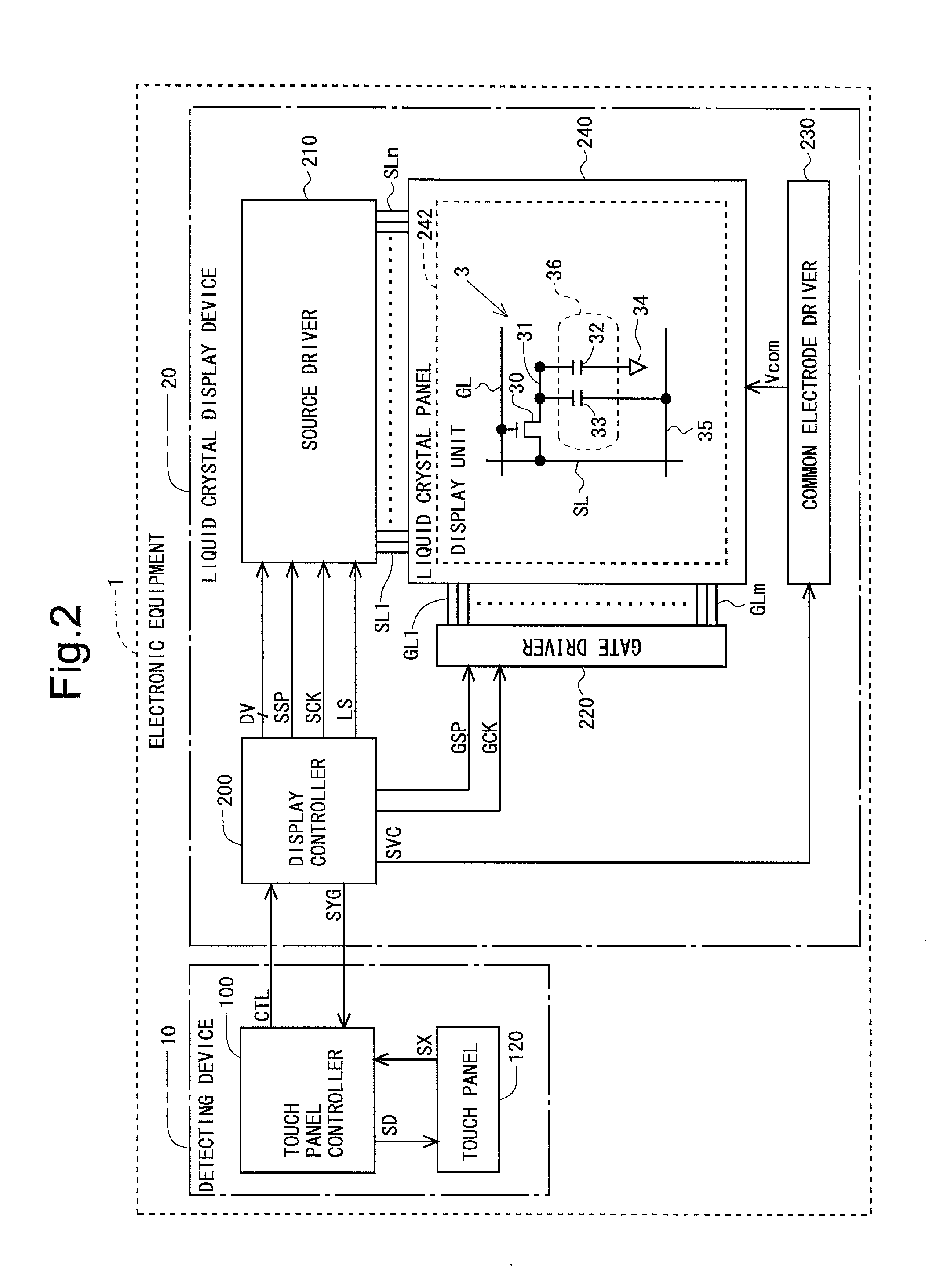
[0096]FIG. 2 is a block diagram showing an overall configuration of electronic equipment 1 including a detecting device 10 according to a first embodiment of the present invention. The electronic equipment 1 is composed of the detecting device 10 and a liquid crystal display device 20. Note that the electronic equipment 1 may further include a controller that mediates the exchange of various types of data between the detecting device 10 and the liquid crystal display device 20.

[0097]The detecting device 10 is composed of a touch panel controller 100 and a touch panel 120. Note that, in the present embodiment, a detection control unit is implemented by the touch panel controller 100, and a sensing unit is implemented by the touch panel 120. The touch panel controller 100 receives a synchronizing signal group SYG which is transmitted from a display controller 200 in the liquid crystal display device 20, and outputs drive signals SD for performing a location detectio...

second embodiment

2. Second Embodiment

[0132]A second embodiment of the present invention will be described. Note that only differences from the first embodiment will be described.

[0133]An overall configuration is the same as that of the first embodiment (see FIG. 2). FIG. 13 is a block diagram showing a detailed configuration of a detecting device 10 in the present embodiment. In the first embodiment, a vertical synchronizing signal Vsync and a general-purpose input-output signal GPIO are inputted as synchronizing signals SYG to a touch panel controller 100. On the other hand, in the present embodiment, only a general-purpose input-output signal GPIO is inputted as a synchronizing signal SYG to the touch panel controller 100. Other points are the same as those of the first embodiment.

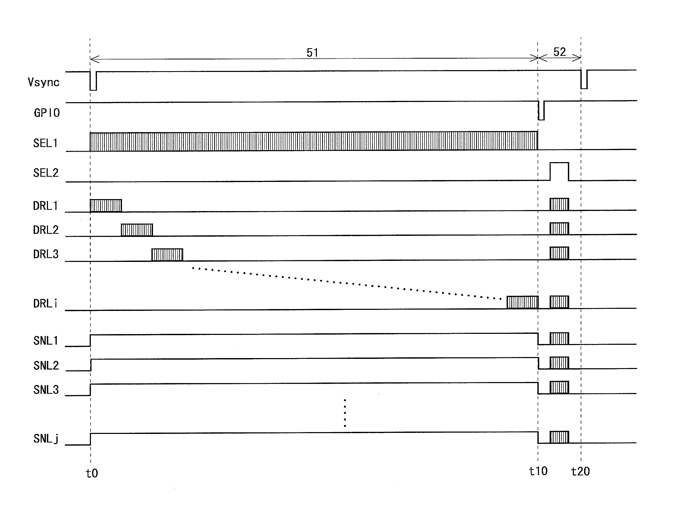
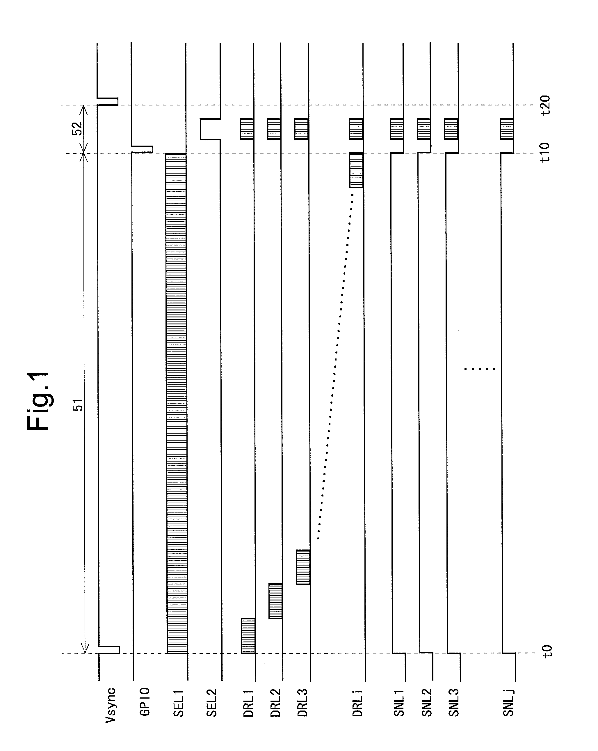
[0134]FIG. 14 is a signal waveform diagram for describing a method of driving a location detection electrode group in the present embodiment. In the present embodiment, during a vertical flyback period 52, all drive line...

third embodiment

[0145]A third embodiment of the present invention will be described. Note that only differences from the first embodiment will be described.

[0146]An overall configuration is the same as that of the first embodiment (see FIG. 2). FIG. 16 is a block diagram showing a detailed configuration of a detecting device 10 in the present embodiment. As shown in FIG. 16, a touch panel controller 100 is provided with a drive switching unit 118 in addition to the components in the first embodiment (see FIG. 3). In addition, in the present embodiment, a vertical synchronizing signal Vsync, a horizontal synchronizing signal Hsync, and a general-purpose input-output signal GPIO are inputted as a synchronizing signal group SYG to the touch panel controller 100.

[0147]When the drive switching unit 118 detects a predetermined matter (hereinafter, referred to as “switching factorial matter”) Msw, the drive switching unit 118 provides switching signals SWa, SWb, and SWc to a timer 114, a signal selecting ...


PUM


Abstract

A detecting device that can sufficiently exhibit its performance even when used integrally with a high-resolution display device is implemented. In a detecting device that can perform a location detection process using both of a self-capacitance scheme and a mutual-capacitance scheme, a touch panel controller drives a location detection electrode group formed in an area where location detection by the location detection process is to be performed, for example, such that the location detection process using the self-capacitance scheme is performed during a vertical flyback period (52) and the location detection process using the mutual-capacitance scheme is performed during horizontal flyback periods within an effective vertical scanning period (51). As such, when the location detection process is performed using at least one of the self-capacitance scheme and the mutual-capacitance scheme, the touch panel controller drives the location detection electrode group based on a synchronizing signal.

Description

TECHNICAL FIELD[0001]The present invention relates to, for example, a detecting device having a touch panel, and more particularly to a detecting device that is used integrally with a display device and that is capable of performing location detection using both of a self-capacitance scheme and a mutual-capacitance scheme.BACKGROUND ART[0002]As an input device for performing operations in a computer system, etc., attention is focused on a touch panel conventionally. In an electrostatic capacitance type touch panel, a location of an object to be detected, such as a user's (operator's) finger or a touch pen, is detected based on a change in electrostatic capacitance. Such an electrostatic capacitance type touch panel is generally used integrally with a display device such as a liquid crystal display device. Note that, in this specification, a device composed of a touch panel and a controller (touch panel controller) that controls the operation of the touch panel is referred to as “det...

Claims


Application Information

Patent Timeline
IPC IPC(8): G06F3/041G06F3/044
CPCG06F3/0416G06F2203/04106G06F3/0412G06F3/044G06F3/041662G06F3/04184G06F3/0446
Inventor MAYUMI, MASASHI
Owner SHARP KK
Why Eureka
Try Eureka