

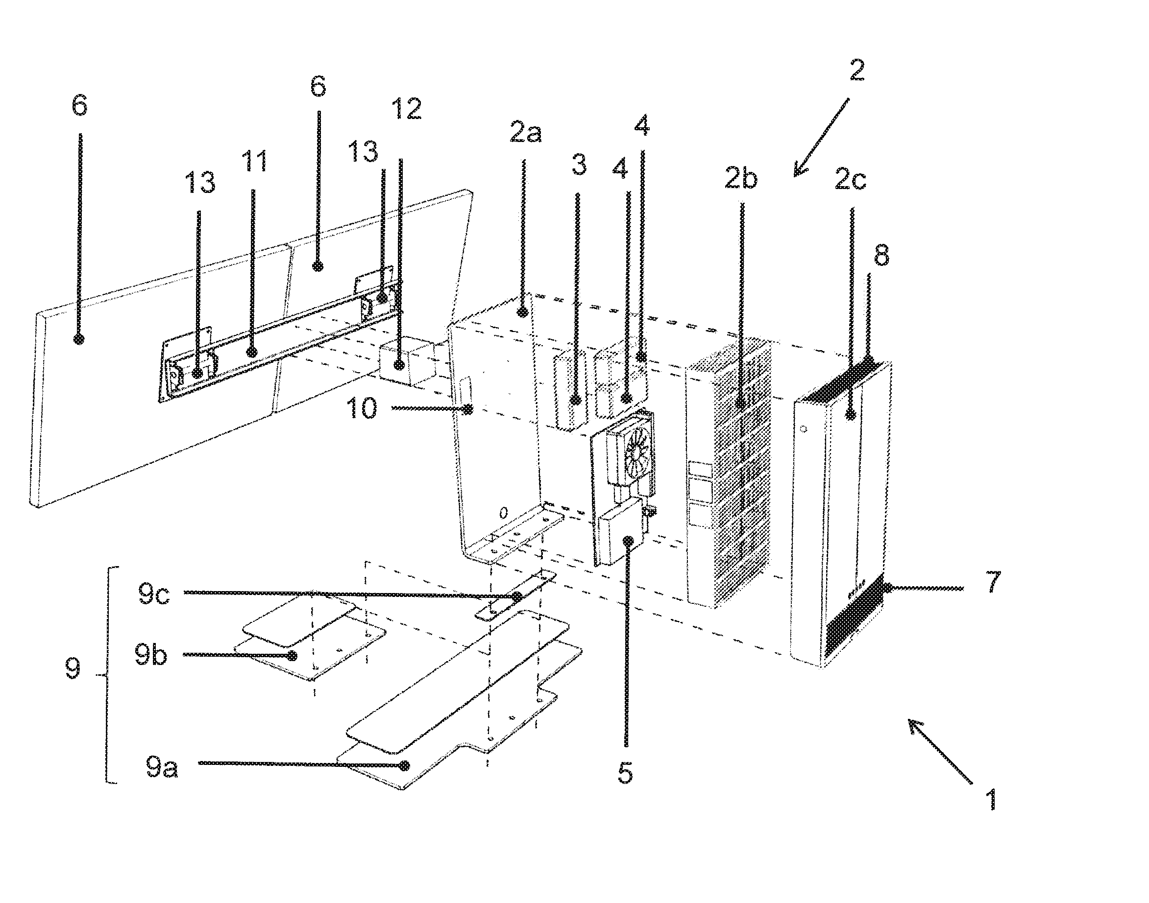
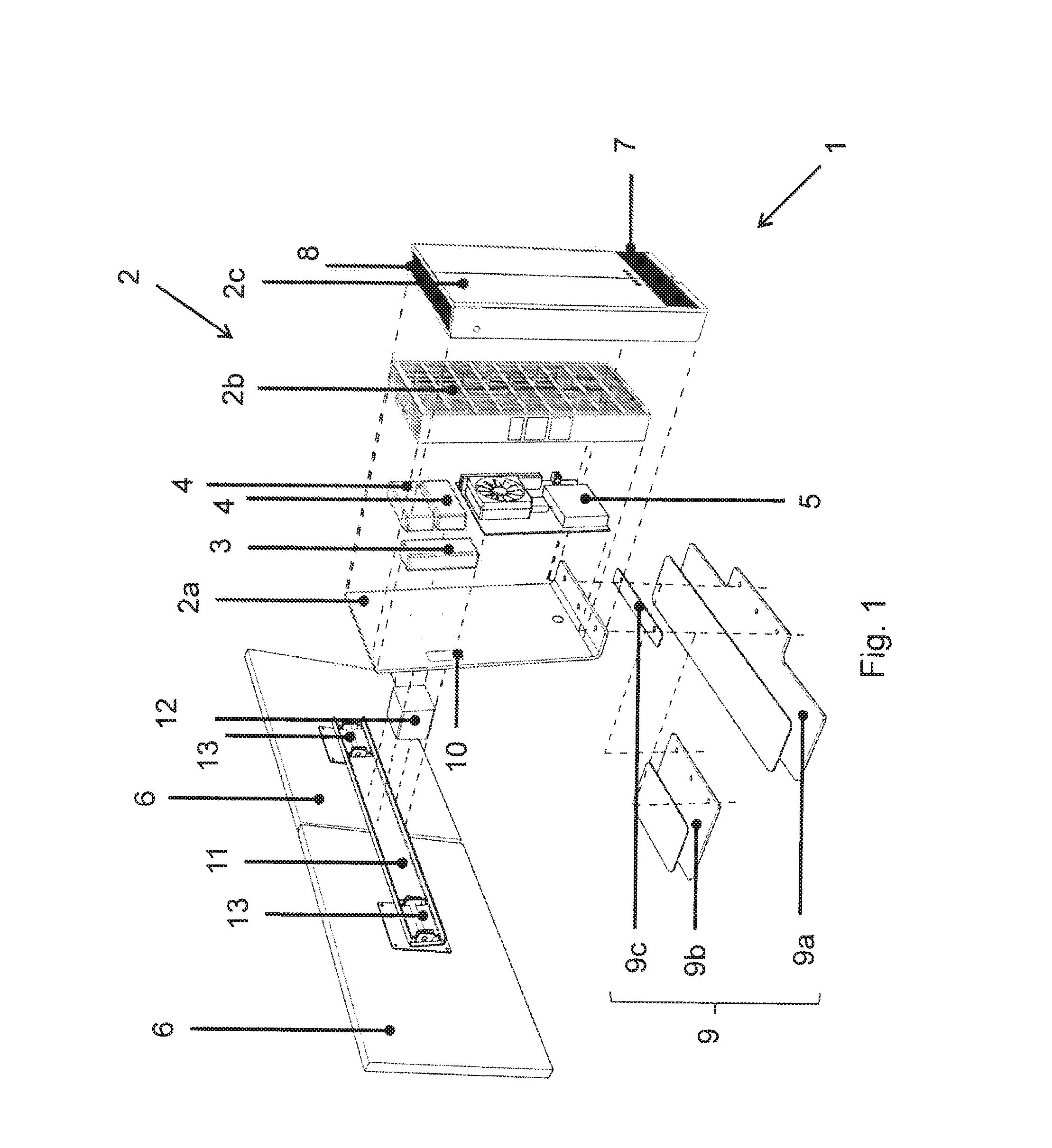
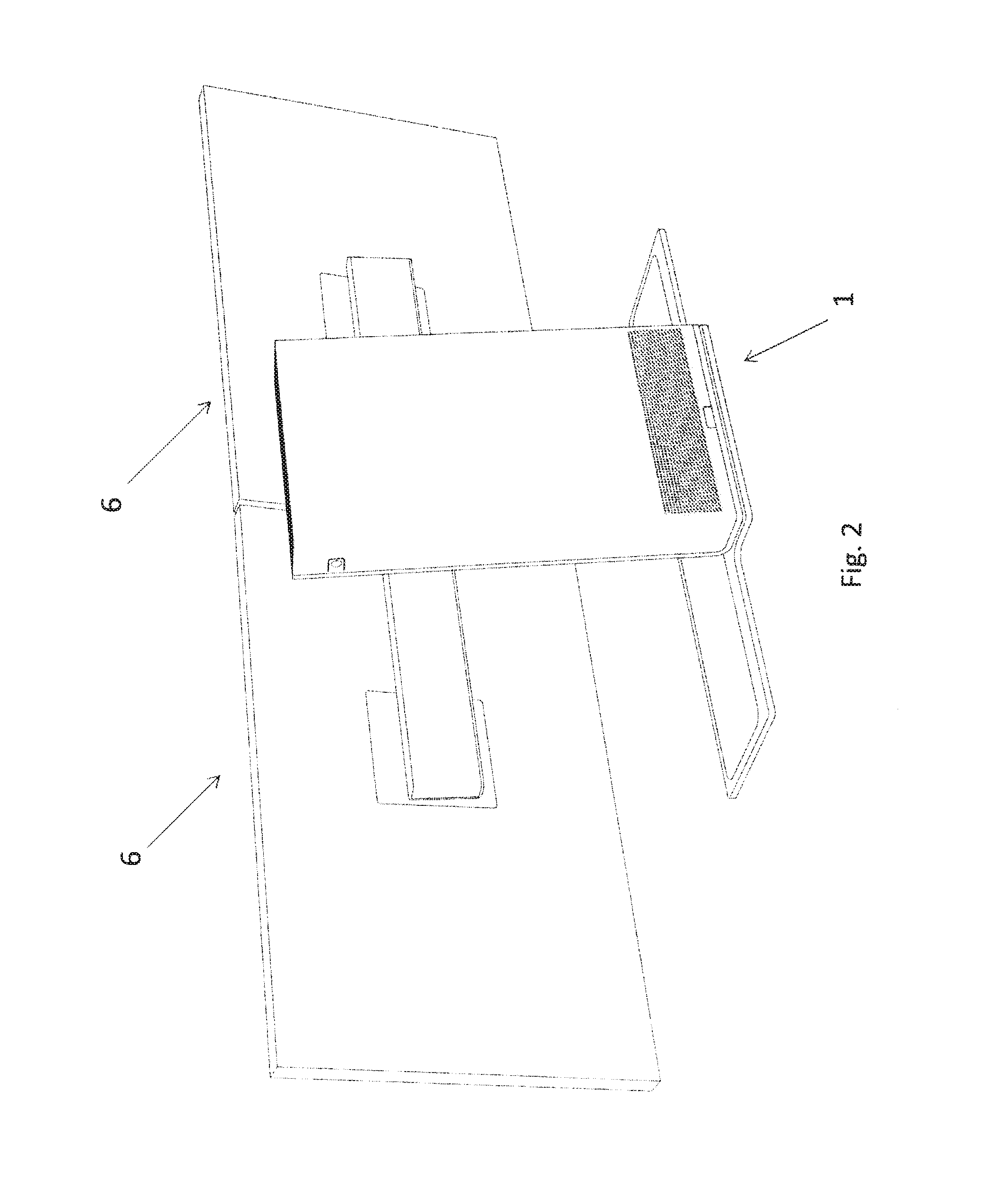
Screen rack for two screens with a case for electric components
a technology for electric components and racks, applied in the direction of machine supports, furniture parts, instruments, etc., can solve the problem that single screens with a large screen format are generally more expensive than two
- Summary
- Abstract
- Description
- Claims
- Application Information
AI Technical Summary
Benefits of technology
Problems solved by technology
Method used
Image

Examples
case 2
Case 2 for Electric Components
[0028]According to the invention, the screen rack 1 comprises a cuboid-shaped and upward aligned case 2 to integrate electric components. In particular, the power supply adapters for a PC 5 and for screens 6 to be installed on the screen rack 1 are arranged in the case 2. The case 2 comprises a carrying case section and / or support section 2a that is mounted on a large mounting plate 9a via a spacer plate 9c and that is consequently linked to the mounting section 9 in a rigid way. On the side of the carrying case section 2a that points towards the screens 6, an ON / OFF switch is to be installed in a central position below the screens 6. If needed, there are USB slots and / or further ports for external accessories (e.g. SD card slot, etc.) on the side of the carrying case section 2a that points towards the screens 6 or on the two side areas of the case 2. The carrying case section 2a is essentially designed in a rectangular and plate-shaped manner and forms...
PUM
 Abstract
Description
Claims
Application Information