Monitoring system and monitoring method

a monitoring system and monitoring method technology, applied in the field of monitoring systems and monitoring methods, can solve the problems of not being able to easily and visually recognize the sound source generating abnormal sounds, and achieve the effect of improving the efficiency of monitoring business

Active Publication Date: 2017-01-19
PANASONIC INTELLECTUAL PROPERTY MANAGEMENT CO LTD
View PDF8 Cites 88 Cited by
  • Summary
  • Abstract
  • Description
  • Claims
  • Application Information

AI Technical Summary

Benefits of technology

[0006]An object of the present disclosure is to provide a monitoring system and a monitoring method that display a sound source appearing o

Problems solved by technology

However, in the literature described above, the disclosed configuration is not assumed to be applied to a surveillance system.
Therefore, in the surveillance system in the related art,

Method used


Image

  • Monitoring system and monitoring method
  • Monitoring system and monitoring method
  • Monitoring system and monitoring method

Examples


Embodiment Construction

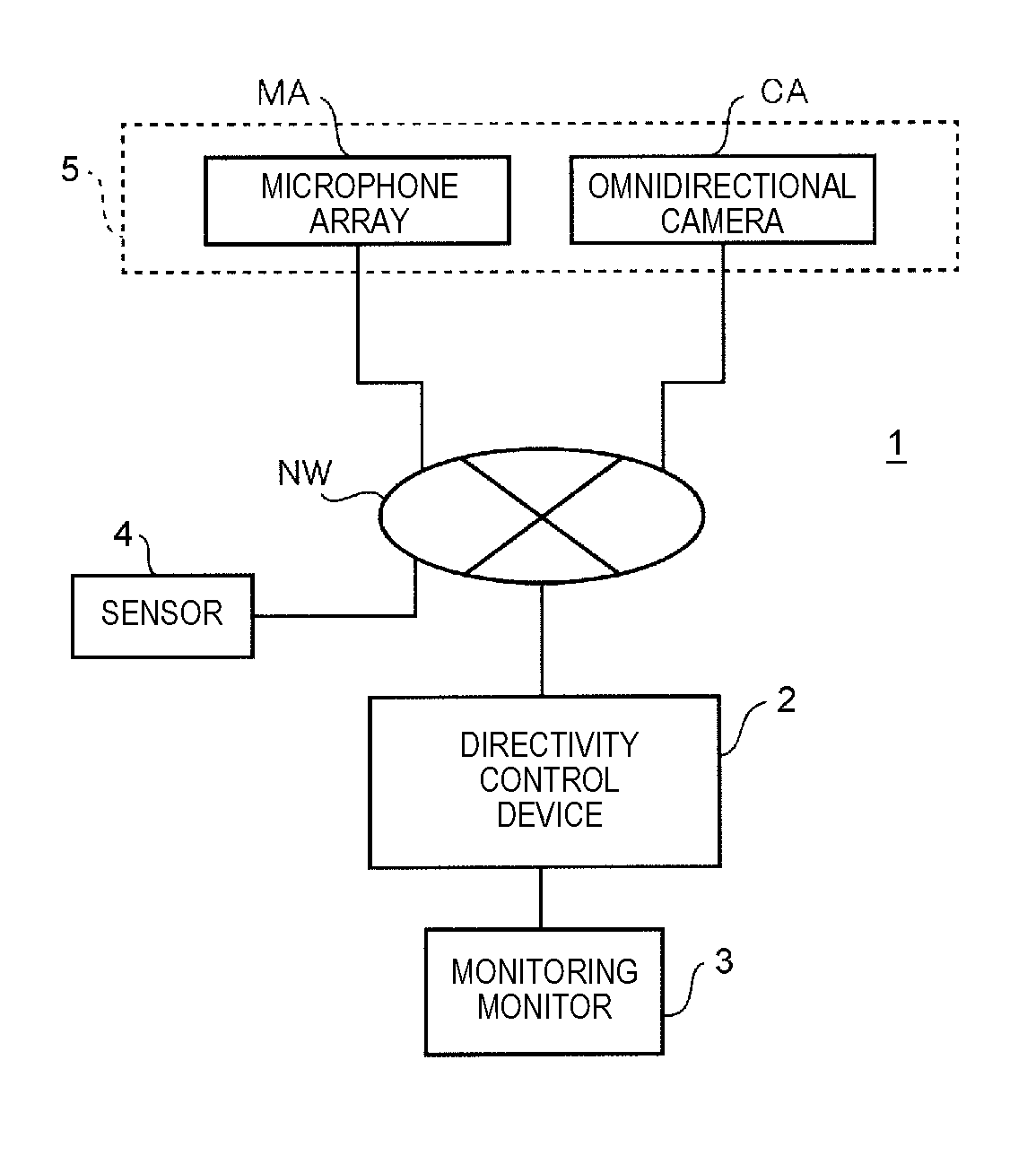
[0023]Hereinafter, embodiments (hereafter, referred to as the present embodiments) which specifically disclose a monitoring system and a monitoring method according to the present disclosure will be described in detail with reference to the appropriate drawings. However, in some cases, descriptions more detailed than required will be omitted. For example, in some cases, a detailed description for widely known items or a repeated description of substantially the same configuration will be omitted. This is to prevent the description from becoming unnecessary redundant and to facilitate the easy understanding for those skilled in the art. The drawings attached hereto and the description hereinafter are provided in order for those skilled in the art to sufficiently understand the present disclosure, and there is no intention to limit the aspects described in the Claims attached hereto. Hereinafter, a sound source display system that displays a sound source appearing on video data obtain...


PUM


Abstract

In a sound source display system, an omnidirectional camera captures an image of a monitoring area. A microphone array collects a voice in the monitoring area. A monitoring monitor displays the image of an imaging area captured by the omnidirectional camera. A sound pressure calculator in a directivity control device calculates a sound pressure indicating a source of a sound in the image of the imaging area using voice data of the voice collected by the microphone array. An output controller in the directivity control device compares the sound pressure and threshold values (first threshold value, second threshold value), and causes sound image information in which the sound pressure is converted into visual information according to the result of comparison, to be displayed on the monitoring monitor so as to be superimposed on the image of the imaging area.

Description

BACKGROUND[0001]1. Technical Field The present disclosure relates to a monitoring system and a monitoring method that display an image indicating a sound source.[0002]2. Description of the Related Art[0003]In recent years, in a surveillance system as an example of a monitoring system, monitoring a fixed monitoring target area is performed using voice data collected by a microphone in addition to video data captured by a monitor camera. In this surveillance system, the monitor microphone and the monitor camera are installed in a location separate from a location of a monitor device on which the video data captured by the monitor camera is displayed. By performing the monitoring using the voice data in addition to the video data, in a case of any incident or trouble, a background of the incident or the trouble can be clarified by the voice data in the vicinity of a sound source (that is, origin of the incident or the trouble) appearing in the video data.[0004]In addition, as a head mo...

Claims


Application Information

Patent Timeline
IPC IPC(8): H04R29/00H04N7/18G06K9/00H04R1/32G06V10/147
CPCH04R29/008G06K9/00771H04N7/183H04R1/326H04R1/02H04R1/406H04R3/005H04R19/04H04R2201/401H04R2430/23G06V20/52G06V10/147
Inventor MATSUMOTO, HIROYUKITOKUDA, TOSHIMICHIYOSHIKUNI, SHINTARO
Owner PANASONIC INTELLECTUAL PROPERTY MANAGEMENT CO LTD
Why Eureka
Try Eureka