Plastic Component Comprising a Connecting Element

Active Publication Date: 2017-01-26
BAYERISCHE MOTOREN WERKE AG
View PDF15 Cites 1 Cited by
  • Summary
  • Abstract
  • Description
  • Claims
  • Application Information

AI Technical Summary

Benefits of technology

[0009]The material of the plastic matrix may have, in particular, one or more thermoplastic plastics (thermoplasts) and/or duroplastic plastics (duroplasts). Fiber-reinforced plastics with a thermoplastic matrix have the advantage that they can be afterwards shaped or welded to other thermoplasts. Suitable as thermoplastic plastics are, e.g., polyether ketone (PEEK), polyphenylene sulfide (PPS), polysulfone (PSU), polyether imide (PEI) and/or polytetrafluoroethylene (PTFE). Fiber-reinforced plastics with a duroplastic matrix can no longer be shaped after the hardening or cross linking of the matrix. They have advantageously a high temperature application range. This holds especially for hot-hardening systems, which harden at high temperatures. Fiber-reinforced plastics with duroplastic matrix usually have the highest strength. One can use the following resins, e.g., as duroplastic plastics or the matrix: epoxy resins (EP), unsaturated polyester resin (UP), vinyl ester resin (VE), phenol-formaldehyde resin (PF), diallyl phthalate resin (DAP), methacrylate resin (MMA), polyurethane (PUR), amino resins, melamine resins (MF/MP) and/or urea resin (UF).
[0010]Furthermore, the attachment portion can be of an at least partly spherical shape. The spherical configuration offers the advantage that a second component with a shell-shaped bearing corresponding to the spherical shape and int

Problems solved by technology

Problems arise in the manufacturing of assemblies or subassemblies in which components made of fiber-reinforced plastic and components made of metallic material are combined involving the joining of these components.
Known bonding techniques such as welding cannot be used

Method used


Image

  • Plastic Component Comprising a Connecting Element
  • Plastic Component Comprising a Connecting Element

Examples


Example

DETAILED DESCRIPTION OF THE DRAWINGS

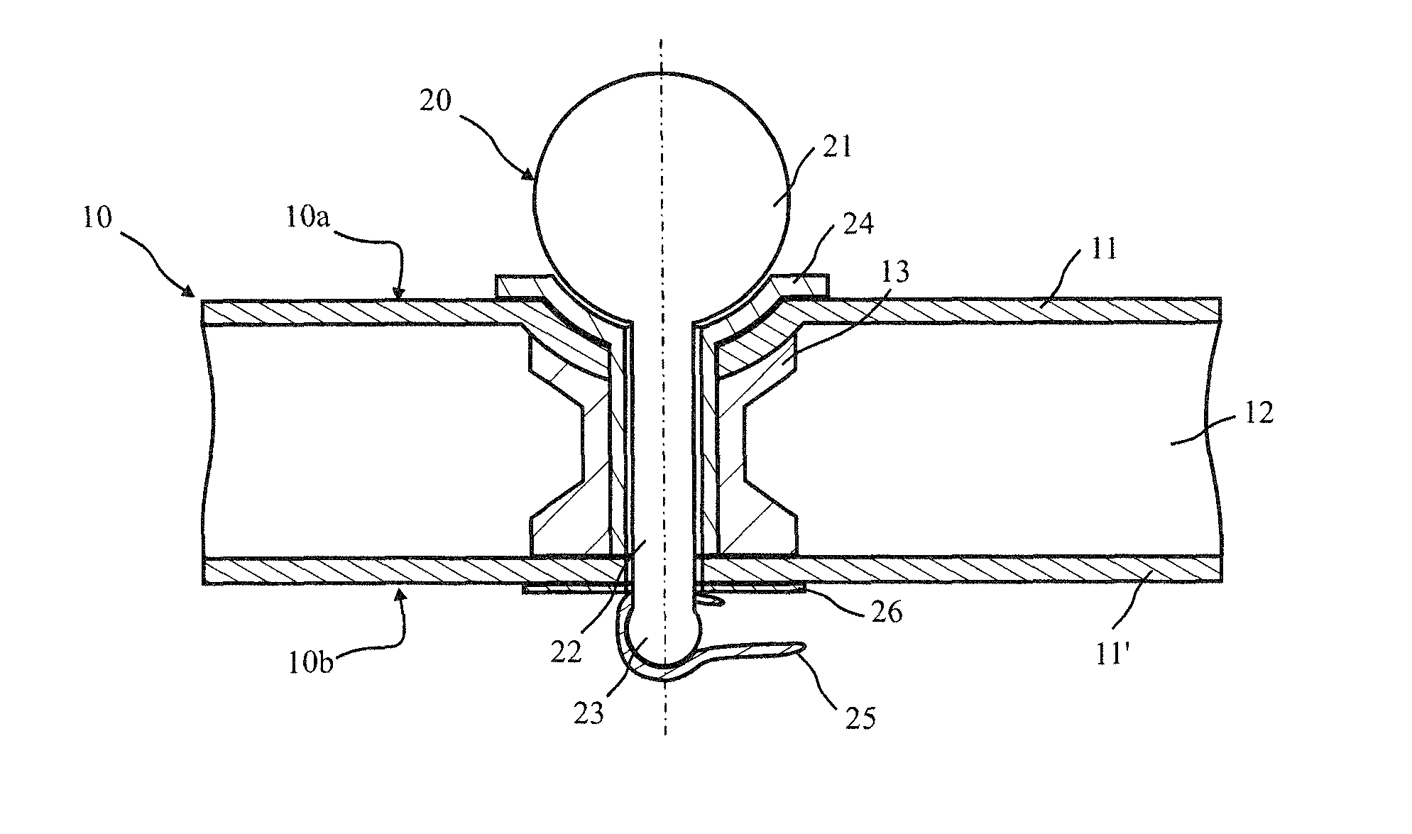
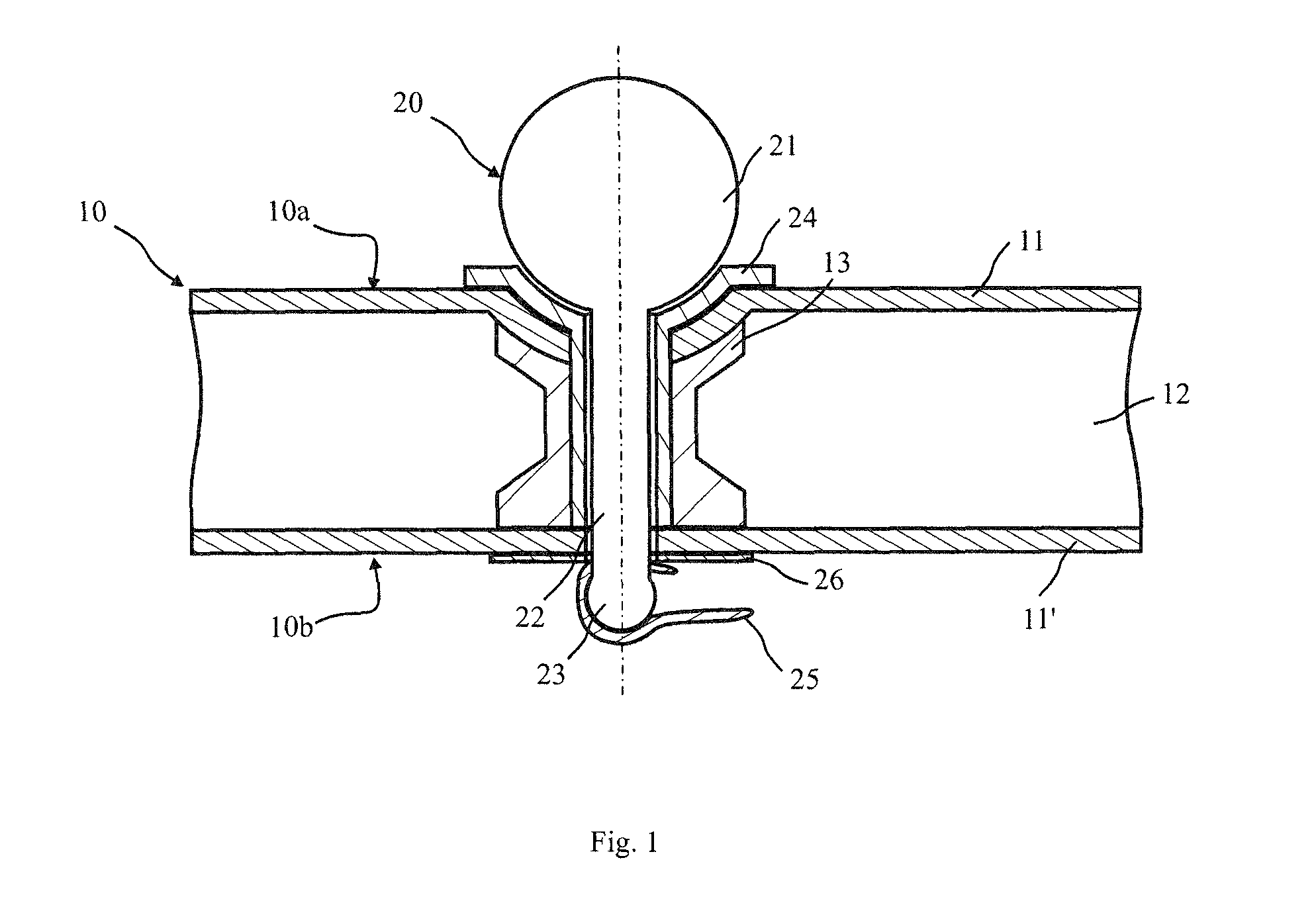
[0022]FIG. 1 shows a sectional view through a plastic component 10 with a connecting element 20 arranged on it. The plastic component 10 is fashioned as a sandwich component with a first reinforcement layer 11, which is shown in FIG. 1 as the top reinforcement layer 11, and a second reinforcement layer 11′, which is shown in FIG. 1 as the bottom reinforcement layer. The reinforcement layers 11, 11′ are formed from a fiber-reinforced plastic, in which reinforcement fibers are incorporated in a matrix material, for example an epoxy resin, of a thermoplastic or duroplastic matrix. The top reinforcement layer 11 forms a first side 10a of the composite component. The bottom reinforcement layer 11′ forms a second side 10b of the composite component 10. Between the reinforcement layers 11, 11′ there is placed a core 12. The core 12 surrounds an insert 13, having an inner borehole or an opening through which at least the connecting element 20 can extend. ...


PUM


Abstract

A plastic component has a connecting element that includes an attachment portion protruding at least in part from the plastic component as well as an anchoring portion, by which the connecting element is releasably connected to the plastic component and which has a smaller cross-sectional diameter than the attachment portion.

Description

CROSS REFERENCE TO RELATED APPLICATIONS[0001]This application is a continuation of PCT International Application No. PCT / EP2015 / 055000, filed Mar. 11, 2015, which claims priority under 35 U.S.C. §119 from German Patent Application No. 10 2014 206 640.9, filed Apr. 7, 2014, the entire disclosures of which are herein expressly incorporated by reference.BACKGROUND AND SUMMARY OF THE INVENTION[0002]The invention relates to a plastic component with a connecting element, wherein the connecting element has an attachment portion protruding at least partly from the plastic component.[0003]In order to reduce emissions and lessen fuel consumption, efforts are being made in modern automobile design to reduce the overall weight of the vehicle. One approach here is the use of new materials, such as fiber-reinforced plastics for example, for the fabrication of structural components or outer skin components that were formerly manufactured for the most part from metallic materials, such as sheet met...

Claims


Application Information

Patent Timeline
IPC IPC(8): F16B5/01F16B21/07F16B5/06
CPCF16B5/01F16B21/073F16B5/0642F16B13/045F16B13/12F16B2/20F16B43/00F16B43/02
Inventor HAMMER, MAIKVAN NIEKERK, JOHANNGREIL, JUERGENLEICHTL, LARSKRUKOWSKI, KATRIN
Owner BAYERISCHE MOTOREN WERKE AG
Why Eureka
Try Eureka