
Gyroscope that Compensates for Fluctuations in Sensitivity

a gyroscope and sensitivity technology, applied in the direction of turning-sensitive devices, acceleration measurement using interia forces, instruments, etc., can solve the problems of affecting the performance of gyroscopes, and affecting the accuracy of gyroscopes

Active Publication Date: 2017-01-26
ANALOG DEVICES INC
View PDF136 Cites 22 Cited by
  • Summary
  • Abstract
  • Description
  • Claims
  • Application Information

AI Technical Summary

Benefits of technology

The invention relates to a method and system for compensating for the sensitivity of an inertial sensor that includes a resonator and an accelerometer. The method involves adding a test signal to the resonator and detecting a phase difference between the test signal and a quadrature error signal from the accelerometer. The detected phase difference is used to determine the bandwidth of the accelerometer, which indicates its sensitivity. The method also includes removing errors from the output rate signal of the accelerometer based on the determined bandwidth. The system includes a sensitivity circuit and a compensating circuit. The sensitivity circuit detects the phase difference and generates a sensitivity signal, while the compensating circuit adjusts the output rate signal based on the sensitivity signal. The technical effect of the invention is to improve the accuracy and reliability of inertial sensor readings.

Problems solved by technology

One problem in the manufacture of MEMS gyroscopes is that the Coriolis signals on which they depend are relatively small.
Such phase shifts are particularly deleterious to gyroscope performance, so it is generally necessary, in practice, to either well separate the frequencies or tightly servo the frequency of the accelerometer to the frequency of the shuttle.
This inevitably interferes with the Coriolis signal and effectively is only applicable to those gyroscopes that do not need static response, such as camera stabilizing gyros.
Generally speaking, quadrature error results when the vibratory motion is not perfectly orthogonal to the accelerometer.
In-phase error results when the vibratory drive force is not perfectly orthogonal to the accelerometer.
One possible approach to reducing gyroscope offset is to attempt to minimize the offset through device design, manufacture, and packaging, but there are practical limits to this approach.
Because the sensitivity can fluctuate due to ambient temperature, the gyroscope may introduce different amounts of error into the rate signal depending on its environment.

Method used


Image

  • Gyroscope that Compensates for Fluctuations in Sensitivity
  • Gyroscope that Compensates for Fluctuations in Sensitivity
  • Gyroscope that Compensates for Fluctuations in Sensitivity

Examples


Embodiment Construction

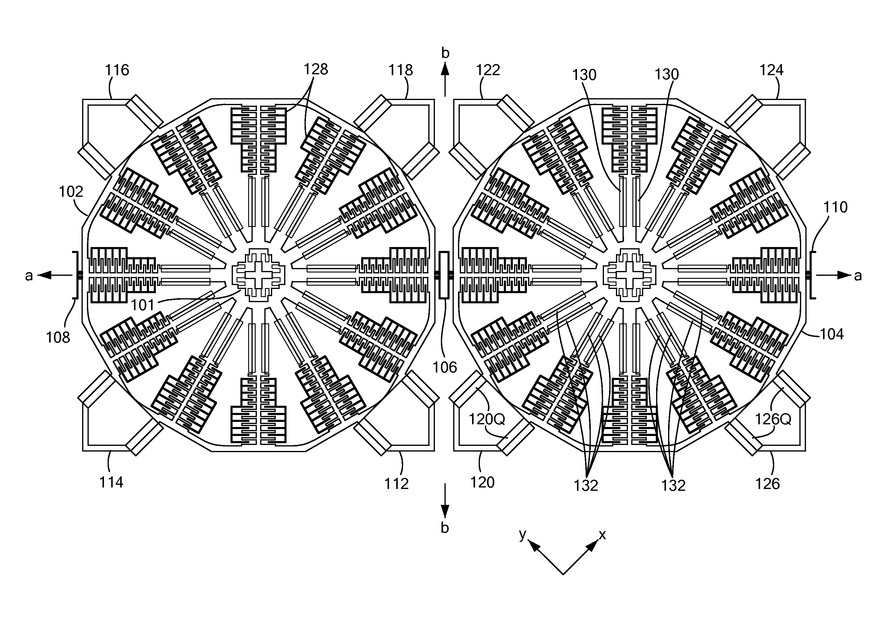
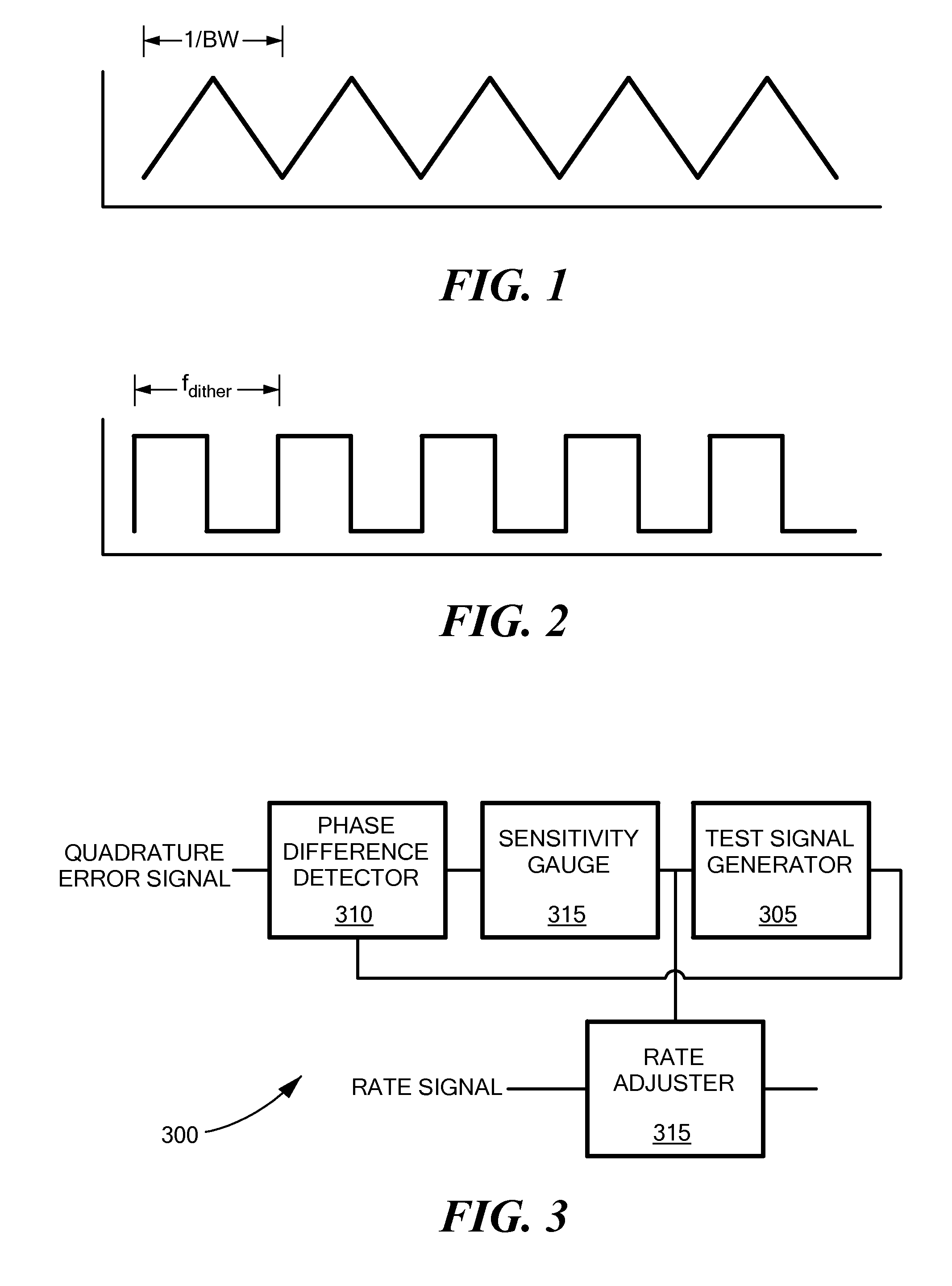
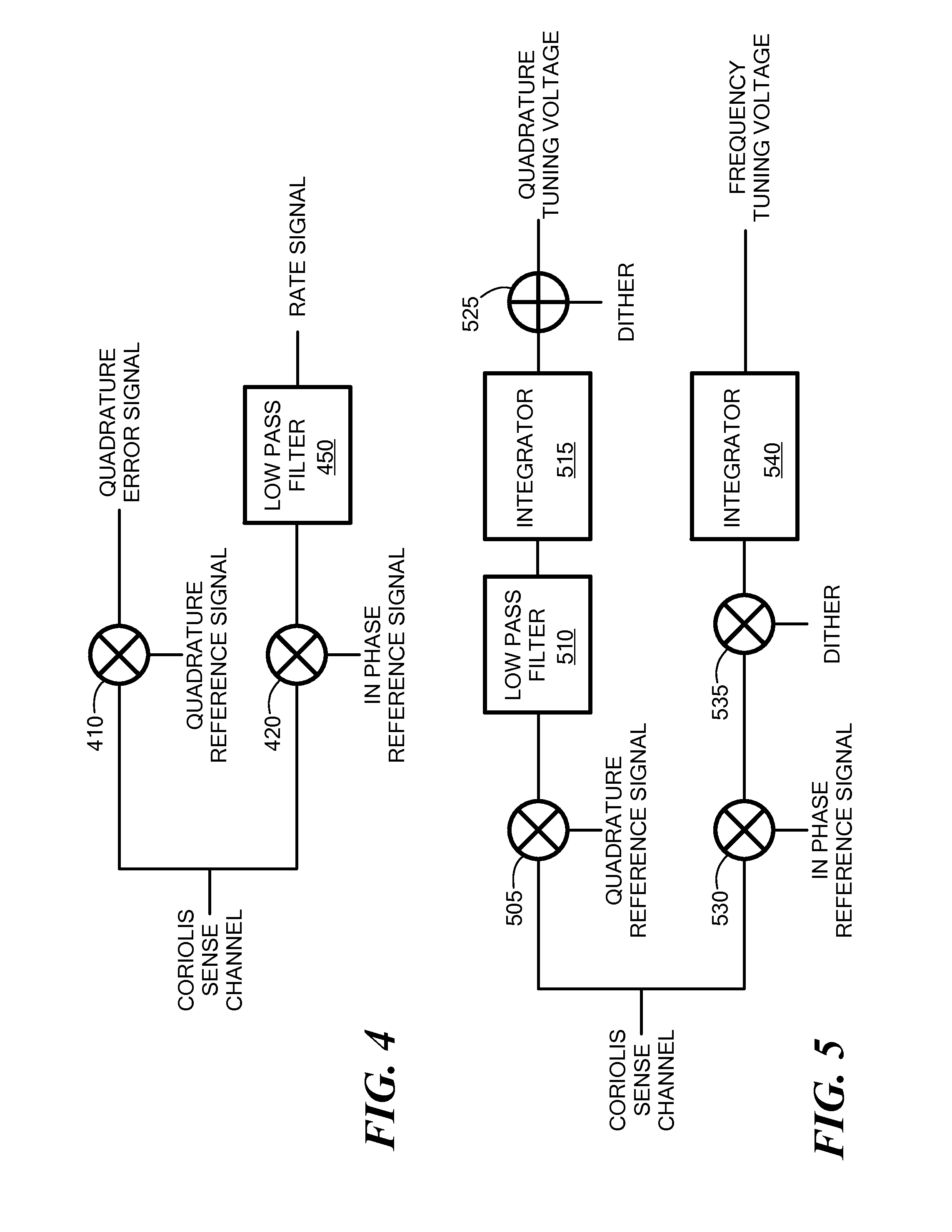
[0012]In one aspect of the invention, a method compensates for a sensitivity of an inertial sensor having a resonator and an accelerometer. The method includes adding a test signal to a quadrature tuning voltage applied to the resonator of the inertial sensor. The method also includes receiving a quadrature error signal from the accelerometer of the inertial sensor. The method also includes detecting a phase difference between the quadrature error signal and the test signal. The method also includes determining a bandwidth of the accelerometer based on the detected phase difference, the bandwidth indicating the sensitivity of the accelerometer.

[0013]The method may also include removing errors from an output rate signal of the accelerometer according to the determined bandwidth of the accelerometer. These errors may be caused by fluctuations in sensitivity of the accelerator.

[0014]In these embodiments, the method may determining the bandwidth of the accelerometer by determining a tim...


PUM


Abstract

A method compensates for a sensitivity of an inertial sensor having a resonator and an accelerometer. The method includes adding a test signal to a quadrature tuning voltage applied to the resonator of the inertial sensor. The method also includes receiving a quadrature error signal from the accelerometer of the inertial sensor. The method also includes detecting a phase difference between the quadrature error signal and the test signal. The method also includes determining a bandwidth of the accelerometer based on the detected phase difference, the bandwidth indicating the sensitivity of the accelerometer.

Description

TECHNICAL FIELD[0001]The present invention relates to adjusting the rate signal of a gyroscope to compensate for the device's sensitivity, and more particularly, to adjusting the frequency of a test signal to determine the sensitivity of the gyroscope.BACKGROUND ART[0002]Micromachined (MEMS) gyroscopes have become established as useful commercial items. Gyroscope performance is very sensitive to such things as manufacturing variations, errors in packaging, driving, linear acceleration, and temperature, among other things. Basic principles of operation of angular-rate sensing gyroscopes are well understood and described in the prior art (e.g., Geen, J. et al., New iMEMS Angular-Rate-Sensing Gyroscope, Analog Devices, Inc., Analog Dialog 37-03 (2003), available at http: / / www.analog.com / library / analogDialogue / archives / 37-03 / gyro.html, which is hereby incorporated herein by reference in its entirety).[0003]The principles of vibratory sensing angular rate gyroscopes with discrete masses ...

Claims


Application Information

Patent Timeline
IPC IPC(8): G01C19/5776
CPCG01C19/5776G01C19/56G01C19/5607G01C19/5642G01C19/5649G01C19/5719G01P15/125G01P15/13G01P21/00
Inventor GREGORY, JEFFREY A.
Owner ANALOG DEVICES INC
Learn More