
Monitoring System and Method for Vessel Mooring

a monitoring system and floating vessel technology, applied in the direction of vessel construction, instruments, transportation and packaging, etc., can solve the problems of mooring system failure, complex installation and maintenance, high installation and maintenance costs, etc., and achieve the effect of limited accuracy of geographic location relating to monitoring a mooring system

Active Publication Date: 2017-01-26
TECH FRANCE SA
View PDF11 Cites 4 Cited by
  • Summary
  • Abstract
  • Description
  • Claims
  • Application Information

AI Technical Summary

Benefits of technology

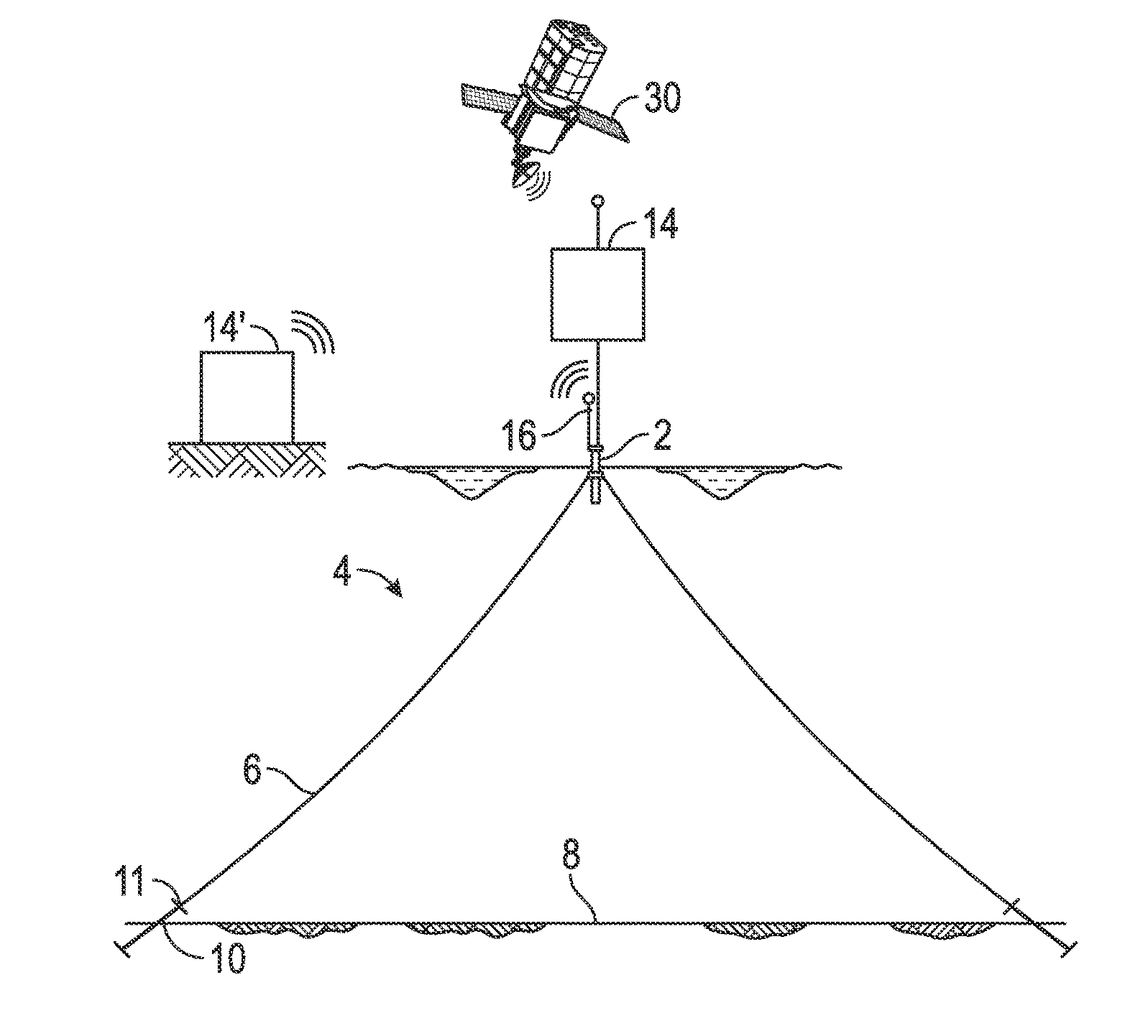
The present invention provides a system and method for monitoring a mooring system for a floating vessel by measuring the movement of the vessel over time to establish the natural period of the device. This natural period can be compared to theoretical values or recorded values to assess any changes in the mooring system, such as a failure or significant damage. The method uses a satellite positioning device and a data processing system to determine the geographical position of the vessel and its associated natural period at a given location. The system can also monitor changes in the mooring line stiffness, riser / export system stiffness shift, and other indicators of a damaged or failing mooring system. This invention allows for early detection of potential hazards and risks associated with mooring systems, improving safety and reliability.

Problems solved by technology

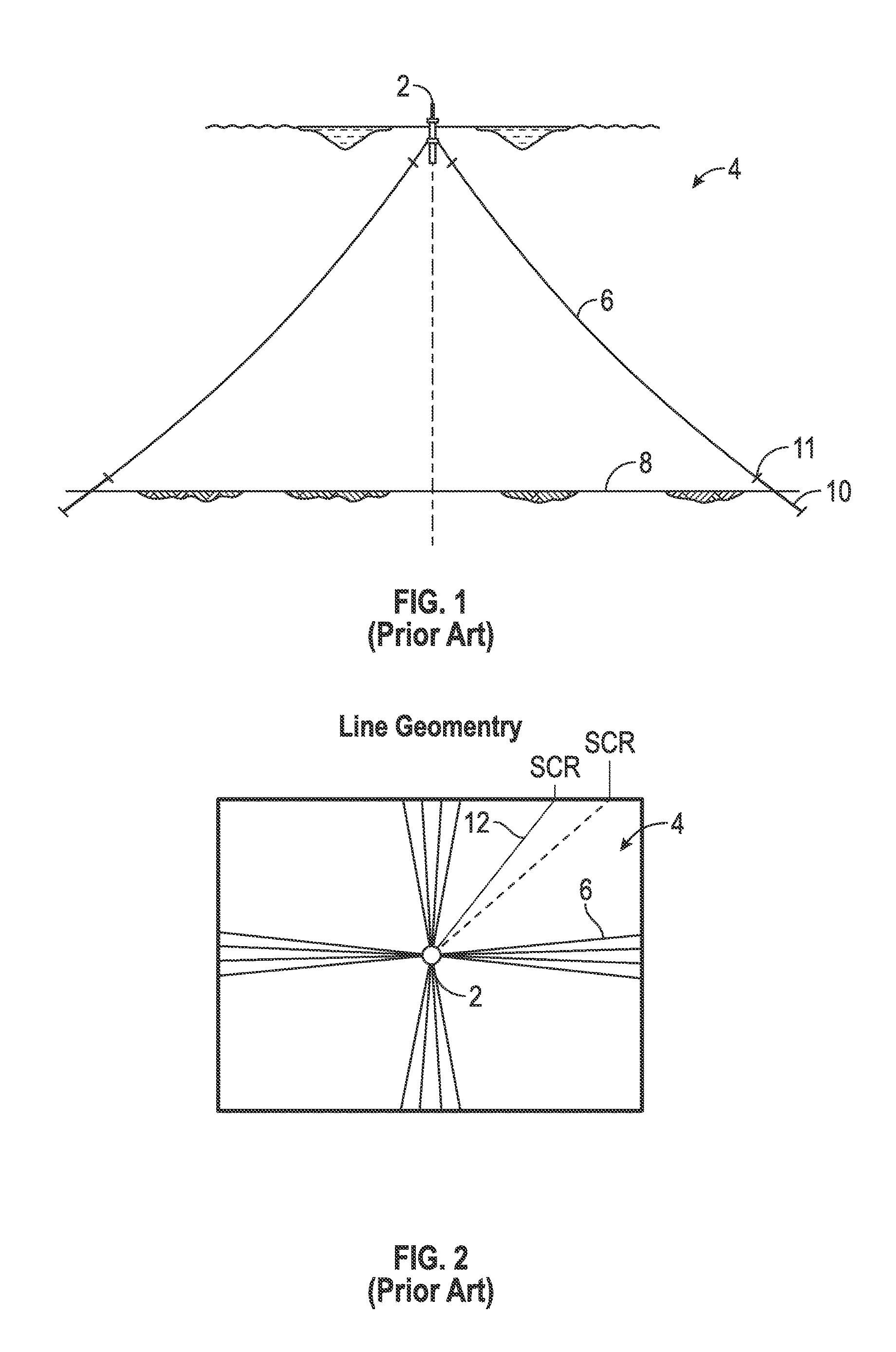
Historically, a typical mooring system failure is discovered during inspection by a diver or ROV.
Such monitoring systems are expensive, complicated to install and maintain, and vulnerable to damage considering that they are installed underwater or close to water.
Because the geographical position varies with environmental conditions such as current flow and direction, wind speed and direction, and so forth, the geographical location by itself related to monitoring a mooring system would appear to have limited accuracy.
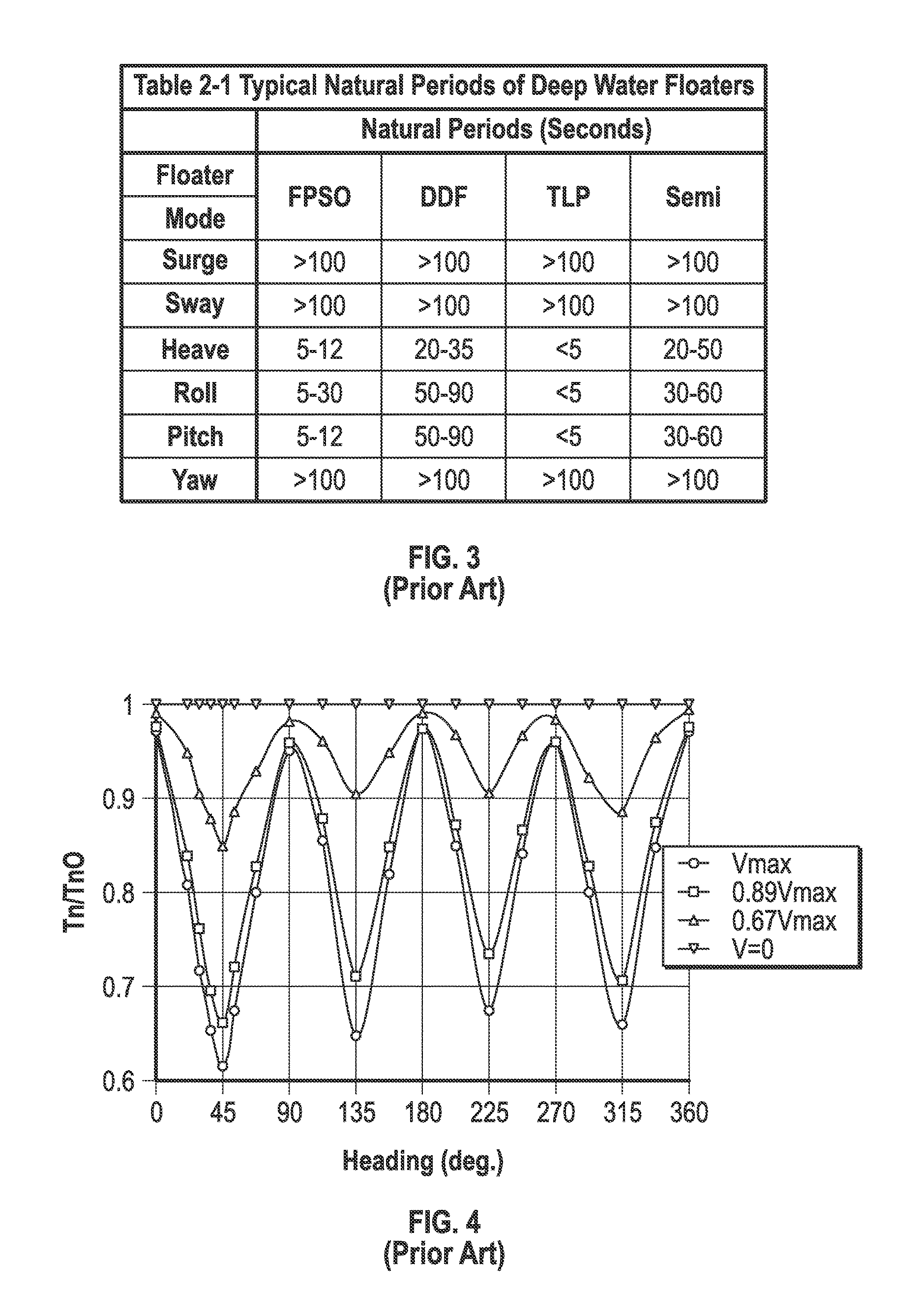
In addition to the above paper not teaching monitoring mooring systems for degradation, the above paper aspects of natural periods but, like US Publication No. 2010 / 0186652, requires environmental factoring to achieve its results.

Method used


Image

  • Monitoring System and Method for Vessel Mooring
  • Monitoring System and Method for Vessel Mooring
  • Monitoring System and Method for Vessel Mooring

Examples


Embodiment Construction

[0031]The Figures described above and the written description of specific structures and functions below are not presented to limit the scope of what Applicant has invented or the scope of the appended claims. Rather, the Figures and written description are provided to teach any person skilled in the art to make and use the inventions for which patent protection is sought. Those skilled in the art will appreciate that not all features of a commercial embodiment of the inventions are described or shown for the sake of clarity and understanding. Persons of skill in this art will also appreciate that the development of an actual commercial embodiment incorporating aspects of the present disclosure will require numerous implementation-specific decisions to achieve the developer's ultimate goal for the commercial embodiment. Such implementation-specific decisions may include, and likely are not limited to, compliance with system-related, business-related, government-related and other con...


PUM


Abstract

The present disclosure provides a system and method of monitoring a mooring system for a floating vessel using the time of the natural period independent of environmental conditions. The natural period can be calculated and / or established experientially over time by measuring movement of the vessel to establish the natural period at given geographical positions of a secure and intact mooring system. The natural period can be monitored based on the time to complete a natural period. A change in a mooring line stiffness, whether by a failure, stretching, a degradation of the mooring line integrity, or a significant displacement of the anchoring point, will be translated into a different natural period with a different time. By monitoring the natural period for a given geographical position (and corresponding heading) to be compared to the theoretical values (and / or previous recorded values) it is then possible to assess that at least a portion of the mooring system has failed or that a significant damage has occurred.

Description

CROSS REFERENCE TO RELATED APPLICATIONS[0001]Not applicable.STATEMENT REGARDING FEDERALLY SPONSORED RESEARCH OR DEVELOPMENT[0002]Not applicable.REFERENCE TO APPENDIX[0003]Not applicable.BACKGROUND OF THE INVENTION[0004]Field of the Invention[0005]The disclosure generally relates to the mooring systems for floating vessels. Specifically, the disclosure relates to the monitoring the condition of mooring systems of floating vessels, including offshore platforms.[0006]Description of the Related Art[0007]In the field of offshore oil and gas production, a moored vessel may be used as a floating drilling and / or production unit (FPU). Typically, an FPU is moored to the sea bed by means of multiple mooring lines attached to anchors, which may typically be pile anchors, suction anchors, or self-burying anchors of conventional type and which maintain the FPU in a desired location. Other vessels, such as offshore floating platforms including Spars, semi-submersible, and other platforms can also...

Claims


Application Information

Patent Timeline
IPC IPC(8): G01C21/20B63B21/50G01S19/42
CPCG01C21/20B63B21/50G01S19/42B63B2021/009B63B21/00B63B2021/003B63B2021/008
Inventor O'SULLIVAN, JR., JAMES FRANCISTCHERNIGUIN, NICOLAS
Owner TECH FRANCE SA
Learn More