Adjacent vehicle detection device

a detection device and parallel running technology, applied in measurement devices, using reradiation, instruments, etc., can solve the problems of rare chance that a road surface is detected, degradation of responsiveness, etc., to increase the number of times of determining, and suppress the erroneous detection

Active Publication Date: 2017-01-26
NIPPON SOKEN +1
View PDF3 Cites 0 Cited by
  • Summary
  • Abstract
  • Description
  • Claims
  • Application Information

AI Technical Summary

Benefits of technology

[0007]The present disclosure has been made in view of such an issue and has an object to provide a parallel running vehicle detecting apparatus which can suppress erroneous detection and degradation of the responsiveness.
[0009]When it is aimed to prevent the erroneous determination to identify a curbstone, etc. as a parallel running vehicle under one determination condition, it becomes necessary to increase the number of times of determining, resulting in the degradation of the responsiveness. On the other hand, in the parallel running vehicle detecting apparatus described above, the parallel running vehicle determination condition is changed based on the detection history of the second distance sensor. Accordingly, the parallel running vehicle determination condition employed when it is determined that a curbstone, etc. may exist according to the detection history of the second distance sensor is different from the parallel running vehicle determination condition employed when it is determined that a curbstone, etc. does not exist. As a result, without increasing the number of times of determining, it is possible to suppress the erroneous determination and identification of a curbstone, etc. as a parallel running vehicle.
[0011]According to the parallel running vehicle detecting apparatus described above, when the second distance sensor detects an object and when this object is a stationary object, a suspending period or suspending distance is set up as a period or distance in which this object passes through the detection area of the first distance sensor. The determining on the basis of the detection result of the first distance sensor is performed after the suspending period elapses or the suspending distance is traveled by the vehicle. Therefore, it is possible to suppress erroneously detecting the stationary object detected by the second distance sensor as a parallel running vehicle. Except for the suspending period or except for a time when the vehicle is traveling the suspending distance, the need of increasing the number of times of determining in order to suppress erroneous detection is reduced. That is, except for the suspending period or except for a time when the vehicle is traveling the suspending distance, it is possible to decrease the number of times of determining; accordingly it is possible to suppress the degradation of the responsiveness.
[0014]Accordingly, in the parallel running vehicle detecting apparatus, when it is possible to determine that the object detected by the first distance sensor is standing still, it is determined whether the object is a parallel running vehicle by comparing with the second reference value which is larger than the first reference value employed in determining that the object detected by the first distance sensor is approaching. According to such procedure, when the object determined to be standing still is a stationary object, it is possible to suppress erroneously detecting the stationary object as a parallel running vehicle. The determination of a parallel running vehicle with the use of the second reference value is restricted to the case where the object can be determined to be standing still. When it is possible to determine that the object is approaching, the determination is made with the use of the first reference value smaller than the second reference value. Therefore, it is possible to suppress the degradation of the detection responsiveness.
[0016]According to the present parallel running vehicle detecting apparatus, when the second distance sensor has detected the object, it is determined whether the object detected by the first distance sensor is a parallel running vehicle, only when the first detection distance to the object detected by the first distance sensor is smaller than the second detection distance to the object detected by the second distance sensor. Therefore, it is possible to detect a motorcycle which is going to pass through the immediate side of an own vehicle as a parallel running vehicle, and at the same time, it is possible to suppress the erroneous detection to identify a stationary object, such as a curbstone and an electric pole, as a parallel running vehicle. Since it is possible to suppress the erroneous detection in this way, the need of increasing the number of times of determining in order to suppress the erroneous detection is reduced. Therefore, it is possible to suppress the degradation of the responsiveness.

Problems solved by technology

In addition, there is a rare chance that a road surface is detected as an obstacle on a road.
However, it is likely that the increase in the number of times of detection will result in the degradation of the responsiveness.

Method used


Image

  • Adjacent vehicle detection device
  • Adjacent vehicle detection device
  • Adjacent vehicle detection device

Examples


embodiment 1

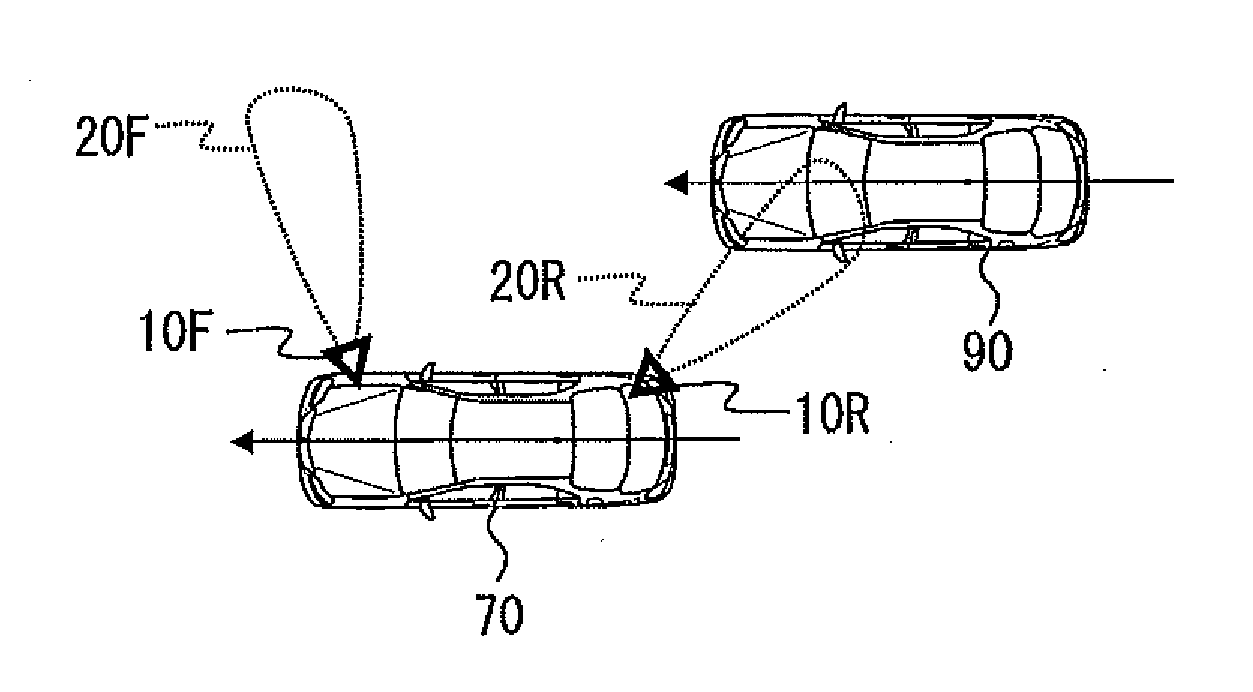
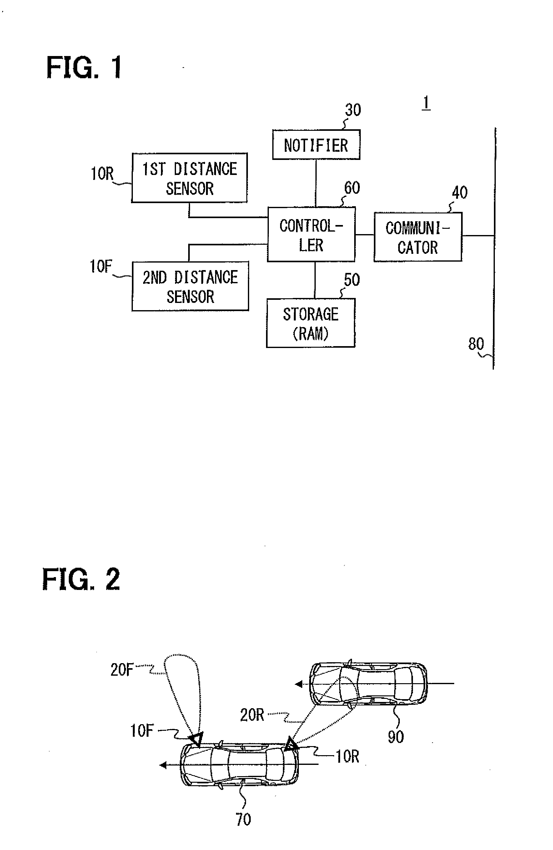
[0041]Hereinafter, embodiments of the present disclosure will be explained in detail with reference to the accompanying drawings. As illustrated in FIG. 1, a parallel running vehicle detecting apparatus 1 according to Embodiment 1 is provided with a first distance sensor 10R, a second distance sensor 10F, a notifier 30, a communication device 40, a storage 50, and a controller 60. The parallel running vehicle detecting apparatus 1 configured in this way is mounted in a vehicle 70 (refer to FIG. 2).

[0042]The pair of the first distance sensor 10R and the second distance sensor 10F is ultrasonic sensors, and they are arranged so as to have a detection area nearest to a vehicle and on a lateral side of either right or left of the vehicle. Here, the lateral side does not restrict the position in the anteroposterior direction to the range from a front end to a back end of the vehicle; however, it also includes a diagonal front (front lateral side) and a diagonal rear (rear lateral side) o...

embodiment 2

[0075]Next, Embodiment 2 is explained. In the explanation of Embodiment 2 and subsequent embodiments, the same elements as explained already are referred to by the same references as used in previous embodiments, unless otherwise referred to in particular.

[0076]In Embodiment 1, the first parallel running vehicle determination condition takes into consideration whether the first detection distance d1 is in the metric division that is considered to be the distance to a curbstone, etc., whereas the second parallel running vehicle determination condition does not take this into consideration.

[0077]In Embodiment 2, in addition to the first parallel running vehicle determination condition and the second parallel running vehicle determination condition, another condition is provided which determines whether, within a predetermined time or a predetermined mileage, the number of times the object is detected in the same metric division has exceeded a predetermined value.

[0078]Furthermore, in ...

embodiment 3

[0080]Next, Embodiment 3 is explained. The mechanical configuration of Embodiment 3 is the same as that of Embodiment 1, and it has the configuration illustrated in FIG. 1. The difference from Embodiment 1 includes control performed by the controller 60. In Embodiment 3, in lieu of the processing illustrated in FIG. 4, the parallel running vehicle detection S30 illustrated in FIG. 5 is performed.

[0081]First, at Step S31, an instruction for transmission and reception is issued to the first distance sensor 10R and the second distance sensor 10F. At Step S32, it is determined whether the second distance sensor 10F has detected an object.

[0082]When the second distance sensor 10F has detected an object (YES at S32), at Step S33, a stationary object flag is set to ON, and a flag setup time (corresponding to the suspending period) is determined.

[0083]The flag setup time is calculated by dividing a flag setting interval by the current vehicle velocity. In the above, the flag setting interva...


PUM


Abstract

A parallel running vehicle detecting apparatus is provided, which includes a first distance sensor for detecting distance of an object in a first detection area on a rear lateral side of a vehicle, a second distance sensor for detecting distance of an object in a second detection area, a parallel running vehicle detector for detecting a parallel running vehicle based on detections of the first and second distance sensors, and a storage for storing a detection distance history of the second distance sensor. The parallel running vehicle detector is provided with multiple determination conditions for determining whether the object detected by the first distance sensor is the parallel running vehicle, and changes the parallel running vehicle determination condition based on the detection distance history stored in the storage.

Description

CROSS-REFERENCE TO RELATED APPLICATIONS[0001]This application is a divisional application U.S. Ser. No. 14 / 412,581 filed on Jan. 2, 2015 which is a U.S. National Phase Application under 35 U.S.C. 371 of International Application No. PCT / JP2013 / 004182 filed on Jul. 5, 2013 and published in Japanese as WO 2014 / 006919 A1 on Jan. 9, 2014 which is based on and claims the benefit of priority from Japanese Patent Application 2012-152760 filed on Jul. 6, 2012 and Japanese Patent Application 2013-120044 filed on Jun. 6, 2013. The entire disclosures of all of the above applications are incorporated herein by reference.FIELD OF THE INVENTION[0002]The present disclosure relates to a parallel running vehicle detecting apparatus which detects a parallel running vehicle in a blind spot on a vehicle rear lateral side.BACKGROUND[0003]An apparatus disclosed by Patent Document 1 is known as an apparatus which detects a parallel running vehicle existing in a blind spot on a vehicle rear lateral side. I...

Claims


Application Information

Patent Timeline
Patent Type & Authority Applications(United States)
IPC IPC(8): G01S15/93G01S15/931
CPCG01S15/931G08G1/166G08G1/167G01S2015/933
Inventor MATSUURA, MITSUYASUNAKANO, AKIOYOSHIDA, TOORU
Owner NIPPON SOKEN
Why Eureka
Try Eureka