

Photovoltaic generation system and method for using the same
- Summary
- Abstract
- Description
- Claims
- Application Information
AI Technical Summary
Benefits of technology
Problems solved by technology
Method used
Image

Examples
embodiment
DESCRIPTION OF EMBODIMENT
[0049]While the present invention will be described below in detail with reference to the drawings as an example of an embodiment, the present invention is not limited to this.
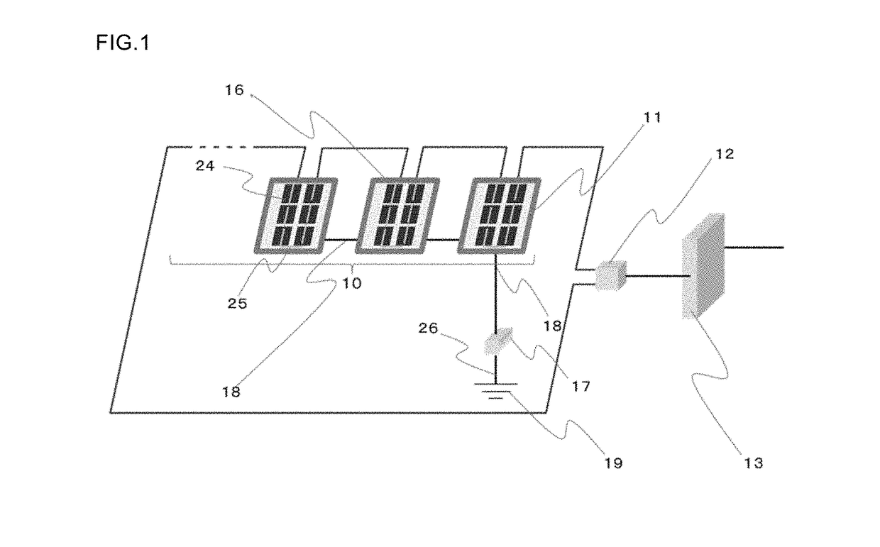
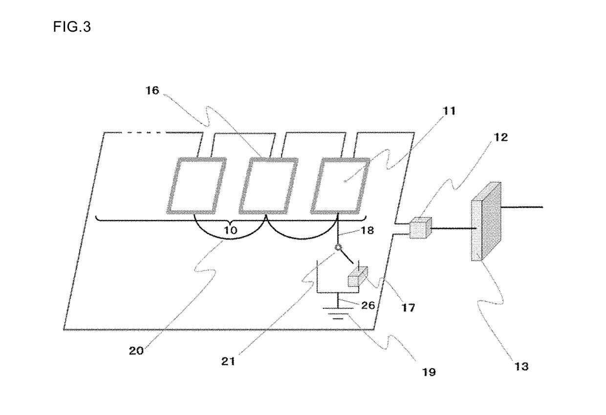
[0050]As mentioned above, while, in a photovoltaic generation system, an earth wire is extracted from a metal frame provided at solar cell module and is connected to a grounding electrode, such connection provides an extremely large potential difference within the module (that is, between the solar cell and the metal frame). There is a problem that this potential difference moves impurity ions present within glass of the solar cell module to inside the glass and further inside a seal material by Coulomb's force, so that impurity ions are forced to the vicinity of the surface of the solar cell, which ruins output characteristics of the solar cells and degrades solar cell module characteristics. This is referred to as PID, which is a serious problem now.
[0051]To address this, while it is...
example 1
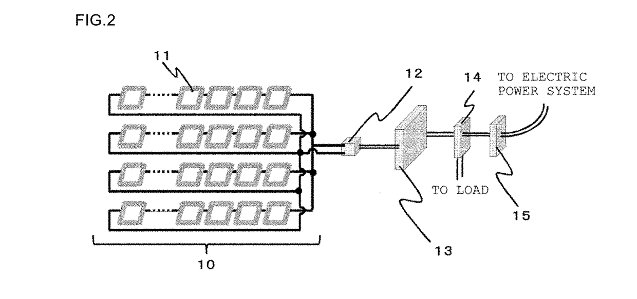
[0095]A photovoltaic generation system of 3.38 kW as illustrated in FIG. 5 was prepared. The solar cell module 11 was a typical silicon solar cell module formed with a single-crystal p-type substrate. The solar cell module was sealed with a seal material, and, further, sandwiched between a white tempered plate glass and a back sheet, and laminated. EVA was used as the seal material, and a sheet obtained by sandwiching both sides of PET (PolyEthylene Terephthalate) with tedlar PVF (Poly Vinyl Fluoride) of Dupon was used as the back sheet. This solar cell module was made by connecting 60 solar cells in series (so-called, 60 series), and had maximum output of 260 W, a nominal open circuit voltage was 37.9 V, and a nominal short-circuit current was 9.10 A. In the present example, these 13 solar cell modules were connected in series and disposed at a sunshiny location. The solar cell modules connected in series in this manner were connected to the power conditioner 13 via the junction bo...
example 2
[0099]A photovoltaic generation system of 5.40 kW as illustrated in FIG. 6 was prepared. The solar cell module 11 was a solar cell module in which silicon solar cells formed with single crystal n-type substrates were connected in series. A seal material and a back sheet which were similar to those in Example 1 were used.
[0100]This solar cell module was 60 series and had maximum output of 270 W, a nominal open circuit voltage was 38.5 V, and a nominal short-circuit current was 9.35 A. In the present example, these 20 solar cell modules were connected in series and disposed at a sunshiny location. The solar cell modules connected in series in this manner were connected to the power conditioner 13 via the junction box 12. At this time, a power conditioner having rated output of 5.5 kW was used as the power conditioner 13. An angle at which the solar cell module 11 was disposed was set at 20° also in the present example in a similar manner to Example 1.
[0101]In the present example, in o...
PUM
 Abstract
Description
Claims
Application Information