Multi-planar camera apparatus

a camera and multi-plane technology, applied in the field of camera equipment, can solve the problems of affecting the functionality of the camera, the limitations of the camera in dynamic rendering 3-d images of a target object, and the inability to use tools, etc., and achieve the effect of enhancing the depth angl

Inactive Publication Date: 2017-01-26
MIRLAY RAM SRIKANTH
View PDF6 Cites 33 Cited by
  • Summary
  • Abstract
  • Description
  • Claims
  • Application Information

AI Technical Summary

Benefits of technology

[0027]Accordingly, the present invention provides a multi-planar camera apparatus in which movable image capturing members that are connected to lateral space variators are arranged to move laterally, horizontally and vertically in multiple planes and to cyclorotate, while capturing 3-D spatial images of the target-subject with enhanced depth angle. The multi-planar camera apparatus is also provided with eye piece complexes and a display unit to view the captured 3-D images directly through human eyes or throu

Problems solved by technology

Also, these camera systems have single eyepiece/objective, which affects their functionality.
However, the cameras of these devices have limitations in dynamic rendering 3-D images of a target object, without resorting to tools such as image processing software to process the spatially-separated visual data.
These cameras also have limitations in providing an enhanced 3-D perception of target-objects from different vantage spatial positions.
In addition, the choice of providing panoramic views of target-objects, from different vantage positions, is not available for such photographic and computing devices.
The de-association of left and right images on two different LCDs would make the simultaneous image viewing cumbersome, as the natural vision of a user converges on either one image, at a given time.
Further, the camera of this type is vulnerable to tilt while capturing images at oblique angles.
The arrangement as disclosed also has a limitation of 3-D triangle of invisibility, which is an area in front of the body of the camera, which cannot be focused on by the converging optical devi

Method used


Image

  • Multi-planar camera apparatus
  • Multi-planar camera apparatus
  • Multi-planar camera apparatus

Examples


Embodiment Construction

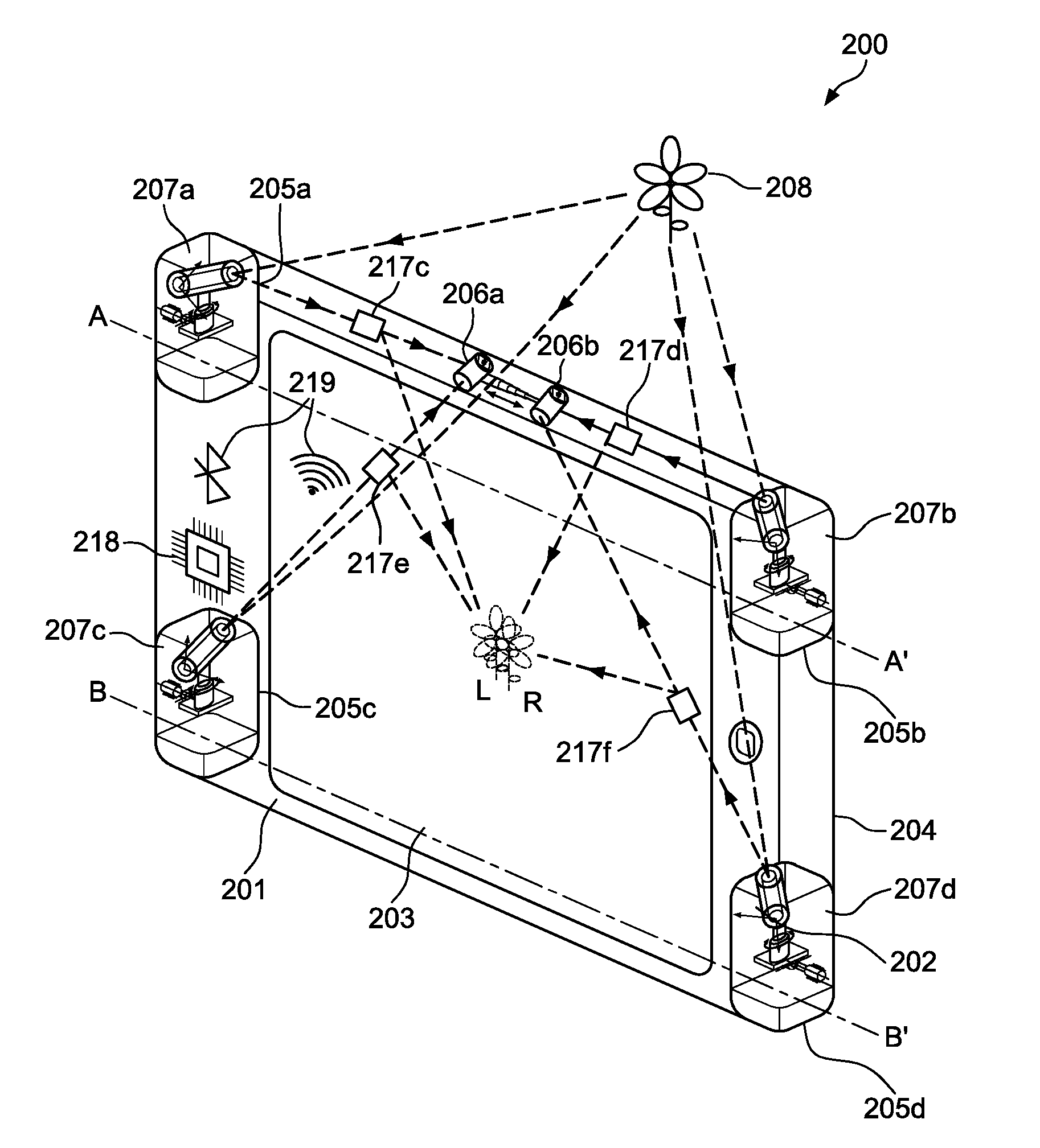
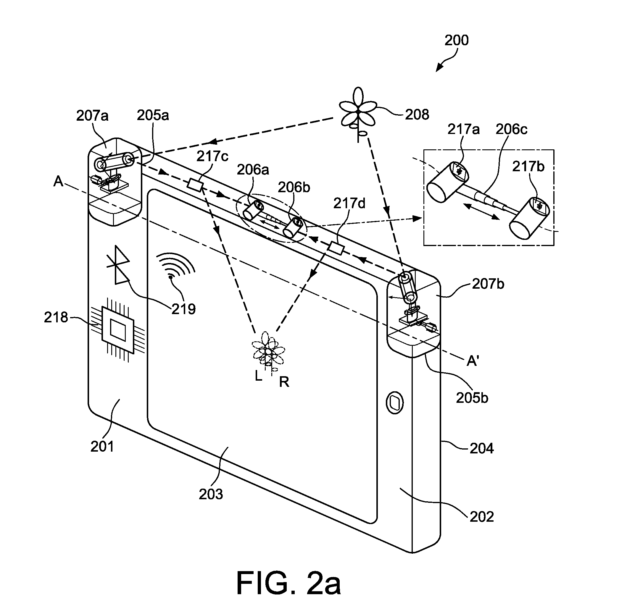
[0049]Depth perception or 3-D vision (length, breadth and depth) of a target-subject is a type of visual experience of a target-subject that normal human / mammals experience with a pair of eyes that are separated by a fixed Inter-Pupillary Distance (IPD). However, those with only one-eye vision can only see the length and breadth of the target-subject but not its depth. Accordingly, when a human being looks at a nearby target-subject, the right and left eyes simultaneously focus, fix or converge on the target-subject, within the limits of the IPD, thereby generating different left and right images, with natural disparity, of the target-subject. These different left and right images of the target-subject are interpreted as 3-dimensional or depth perception by the mechanism of the human brain.

[0050]Similarly, in a 3-D camera, having right and left cameras, the right camera focuses on a target-subject from the right-view perspective and the corresponding left camera focuses on the targe...


PUM


Abstract

The present invention provides a multi-planar camera apparatus in which movable image capturing members that are connected to lateral space variators that are arranged to move laterally, horizontally and vertically in multiple planes and to cyclorotate, while capturing 3-D spatial images of the target-subject with enhanced depth angle and displaying directly through eye piece complexes or through a display unit. The multi-planar camera apparatus of the present invention is provided with a wider field of view to capture panoramic images of target-subjects. Further, the multi-planar camera of the present invention is equipped to capture 3-D spatial images of the target-subject without tilting or turning the body of the camera apparatus. Furthermore, the multi-planar camera apparatus of the present invention obliterates 3-D triangle of invisibility that forms between the image capturing members.

Description

FIELD OF INVENTION[0001]The present invention relates to a camera apparatus, particularly to a multi-planar camera apparatus with image capturing members, to render three-dimensional (3-D) spatial images of a target subject, at various depth angles and in multiple planes. The present invention also relates to a multi-camera apparatus having a wider field of view to capture 2-D panoramic images of a target subject(s).DESCRIPTION OF RELATED ART[0002]Stereoscopic photography in a known way creates a 3-D illusion starting from a pair of 2-D images. The easiest way to enhance depth perception in the brain is to provide the eyes of the viewer with two different images, representing two perspectives of the same object, with a certain deviation approximately equal to the perspectives that both eyes naturally receive in binocular vision.[0003]Stereo lenses which could turn an ordinary film camera into a stereo camera by using a special double lens to take two images and direct them through a...

Claims


Application Information

Patent Timeline
IPC IPC(8): H04N13/02H04N13/04G03B13/02H04N5/225H04N13/243H04N13/239
CPCH04N13/0239H04N5/2253H04N13/0242H04N13/0452H04N2213/001H04N5/2254H04N5/2257H04N13/0296G03B13/02H04N5/2252G03B13/10G03B35/08H04N13/289H04N13/239H04N13/243H04N13/296H04N13/356H04N23/55H04N23/63G03B35/10H04N23/51H04N23/54H04N23/57
Inventor MIRLAY, RAM SRIKANTH
Owner MIRLAY RAM SRIKANTH
Why Eureka
Try Eureka