LED lighting system

a technology of led lamps and led lighting, applied in the direction of electrical appliances, semiconductor devices for light sources, lighting and heating apparatus, etc., can solve the problems of failure of the entire luminaire, labour required for stripping and rewiring the luminaire, negating much, if not all, of the savings involved, and presenting higher costs

Active Publication Date: 2017-01-26
SILICON HILL
View PDF0 Cites 13 Cited by
  • Summary
  • Abstract
  • Description
  • Claims
  • Application Information

AI Technical Summary

Benefits of technology

[0112]The LED lamp arrangement may comprise means for amplifying or deamplifying the current, and feeding the amplified or deamplified current to a sensor. In an embodiment, a first winding of the transformer is arranged in series with the group of one or more LEDs, and a second winding of the trans

Problems solved by technology

However, an LED lamp typically operates differently when used with different ballasts.
In some cases, a straightforward replacement of a florescent lamp by an LED lamp results in a failure of the entire luminaire.
The labour required for stripping and re-wiring the luminaire negates much, if not all, of the savings involved in switching to LED lighting, or even presents higher costs.
The inventors found, surprisingly, that a compatibility issue even exists among electronic ballasts, in particular when the LED lamp requires less energy than the fluorescent tube it is designed to replace.
However, the inventors observed that, once the LED tube is designed to operate at such a low power (e.g. designed to save 50% en

Method used


Image

  • LED lighting system
  • LED lighting system
  • LED lighting system

Examples


Embodiment Construction

[0139]The following is a more detailed explanation of exemplary embodiments of the present invention.

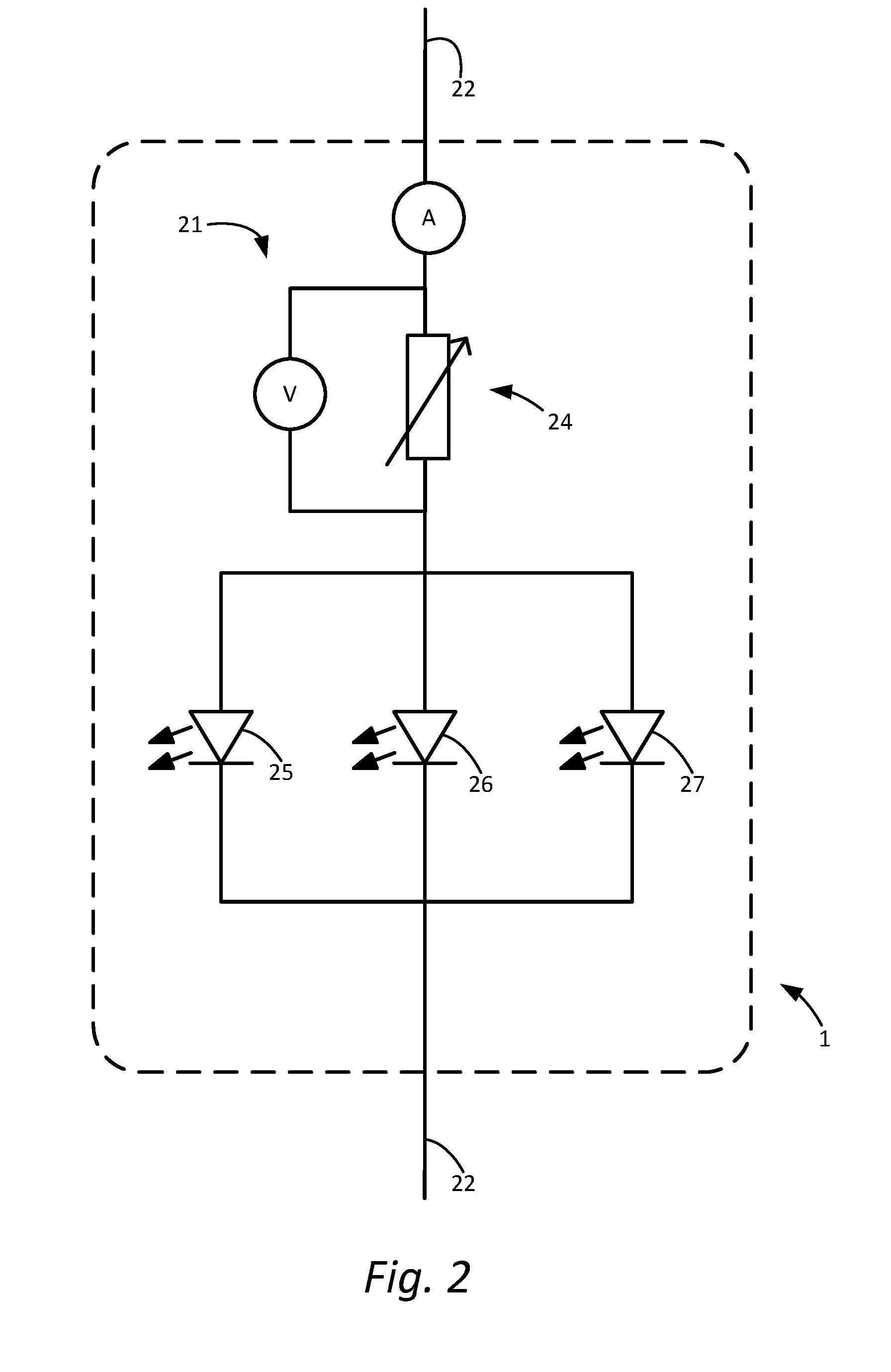
[0140]FIG. 2 shows an embodiment of the LED lamp arrangement 1, comprising a group of one or more LEDs 25, 26, 27, electrodes 22 for releasably connecting to a luminaire and for conducting a current from a ballast for supply to the LEDs, a sensor circuit 21 for measuring a current representing a total current drawn from the ballast by the LED lamp arrangement 1 and / or a voltage representing a voltage supplied by the ballast across the LED lamp arrangement 1, and a protection circuit 24 provided with a variable impedance, arranged in series with the group of LEDs 25, 26, 27. In FIG. 2, the groups 25, 26 and 27 of LEDs represented as a single LED symbol for simplicity, but it should be understood that each group of LEDs may comprise one or more strings of LEDs. In this arrangement, current flowing from the ballast flows through the protection circuit 24 and the group of LEDs 25, 26, 27...


PUM


Abstract

An LED lamp arrangement (1) adapted for fitting in a luminaire. The luminaire is adapted for a fluorescent lamp and having a ballast. The LED lamp arrangement has a plurality of LEDs (25, 26, 27) and two or more electrodes (22) for releasably connecting to the luminaire and for conducting current from the ballast for supply to the LEDs. The LED lamp arrangement further has a sensor circuit (21) and a protection circuit (24). The sensor circuit and the protection circuit are adapted to increase the total load impedance of the LED lamp arrangement if the ballast is a constant power electronic ballast.

Description

CROSS REFERENCE TO RELATED APPLICATIONS[0001]This application is a continuation of PCT application number PCT / EP2016 / 056683, filed on Mar. 24, 2016 which claims priority from Netherlands application number NL2014525, filed on Mar. 26, 2015, and Netherlands application number NL2014530, filed on Mar. 26, 2015. All of the above-mentioned applications are hereby incorporated by reference in their entireties.BACKGROUND OF THE INVENTION[0002]The invention relates generally to LED lamps and LED lighting, and more particularly to LED lamps suitable to replace a fluorescent lamp in a luminaire having a ballast for use with fluorescent lamps.[0003]Fluorescent lighting has been around for many years now. This form of lighting started out as a highly efficient alternative for incandescent light bulbs, but has recently been surpassed by LED lighting to some extent in terms of efficiency and power consumption, and also in other aspects as set out below.[0004]An LED (light emitting diode) is a se...

Claims


Application Information

Patent Timeline
IPC IPC(8): H05B33/08H05B44/00
CPCH05B33/089H05B33/0809H05B33/083H05B45/48H05B45/44H05B45/54H05B45/3725Y02B20/30H05B45/3578H05B45/46F21Y2115/10F21K9/27
Inventor SEGERS, MAARTEN WILLEMROY, SHOUNAKSTEFFENS, PAULGROENENDAAL, TOONHONOLD, JURGEN
Owner SILICON HILL
Why Eureka
Try Eureka