Phoropter, and method for measuring refraction using a phoroptor of said type

Active Publication Date: 2017-02-02
ESSILOR INT CIE GEN DOPTIQUE
View PDF18 Cites 28 Cited by
  • Summary
  • Abstract
  • Description
  • Claims
  • Application Information

AI Technical Summary

Benefits of technology

[0011]Thus a compact orientable assembly is obtained allowing visual acuity measurements to be carried out in

Problems solved by technology

This solution is impractical and requires trial lenses to be stored separately in dedicated boxes.
It furthermore involves lens changes, resulting in undesired and non-continuous transitions in corrective power.
However, it will be unde

Method used


Image

  • Phoropter, and method for measuring refraction using a phoroptor of said type
  • Phoropter, and method for measuring refraction using a phoroptor of said type
  • Phoropter, and method for measuring refraction using a phoroptor of said type

Examples


Embodiment Construction

[0029]The following description, given with regard to the appended drawings and by way of nonlimiting example, will allow what the invention consists of and how it can be carried out to be well understood.

[0030]In the appended drawings:

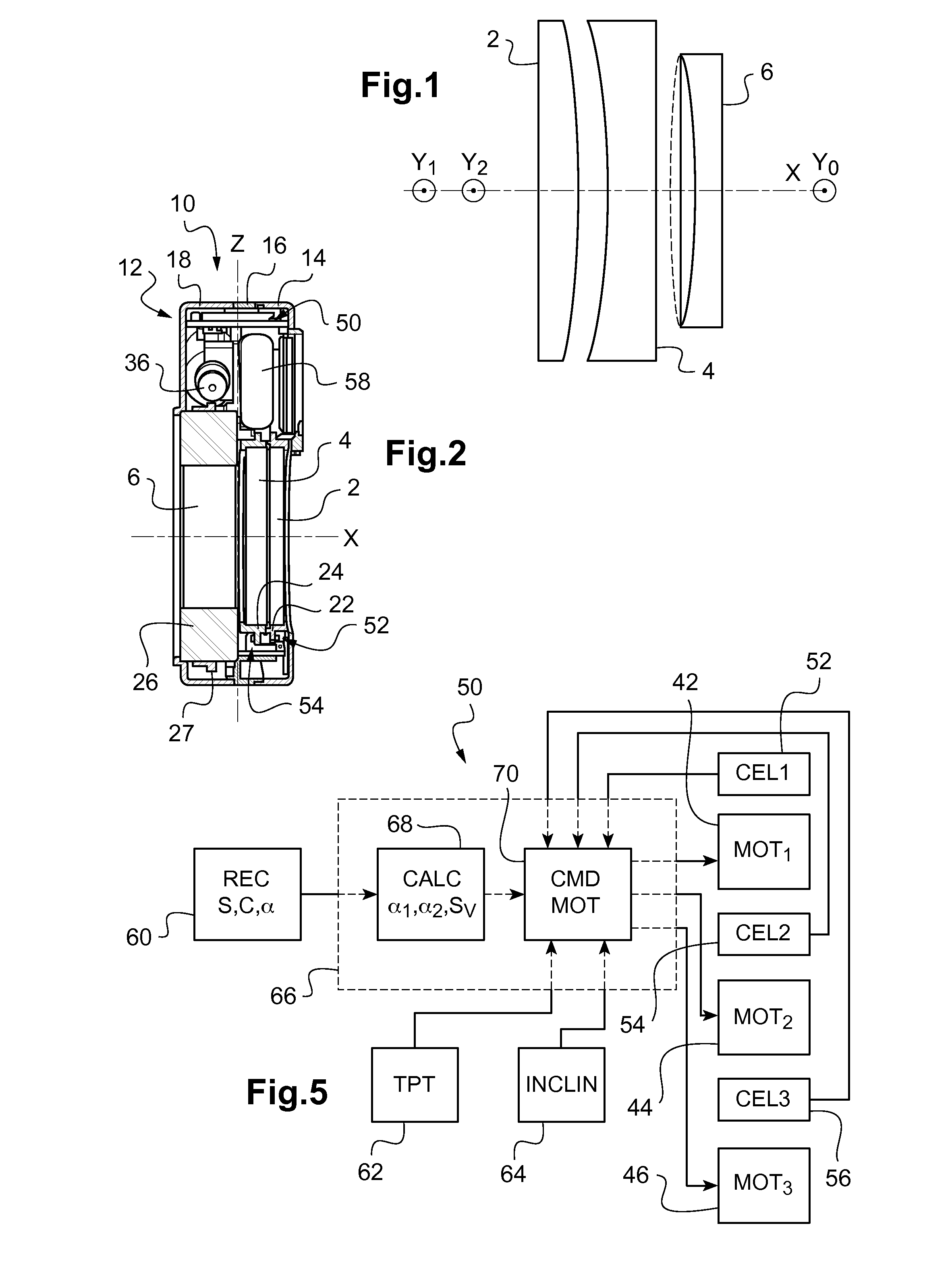
[0031]FIG. 1 schematically shows the optical elements used in one example implementation of the invention;

[0032]FIG. 2 shows a cross-sectional view of an example vision compensating device that may be used in the context of the invention;

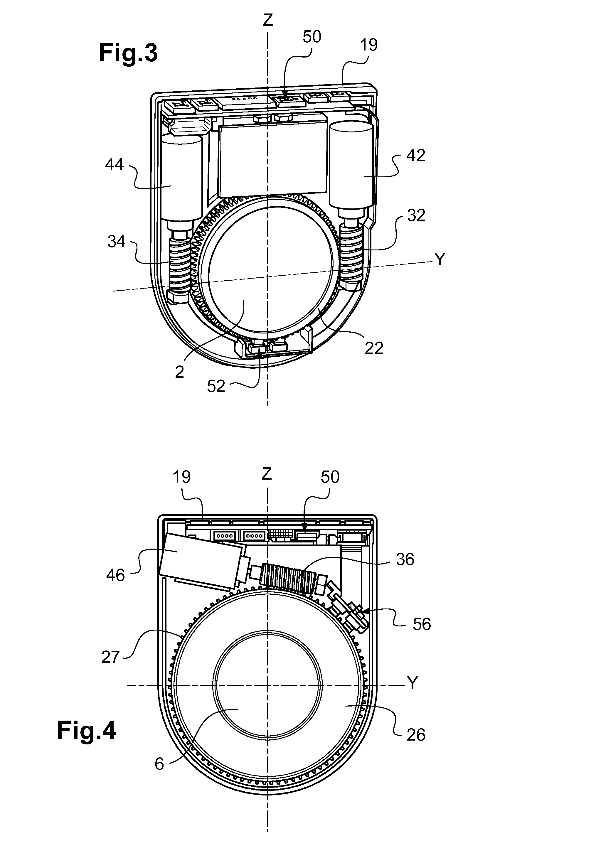
[0033]FIG. 3 shows a cutaway view of the vision compensating device in FIG. 2, on the cylindrical lens side;

[0034]FIG. 4 shows a cutaway view of the vision compensating device in FIG. 2, on the variable spherical lens side;

[0035]FIG. 5 schematically shows an element for controlling the vision compensating device in FIG. 2;

[0036]FIG. 6 is a perspective view of a refractor according to the teachings of the invention in a first configuration intended for testing far vision;

[0037]FIG. 7 is a perspective view of the refrac...


PUM


Abstract

A refractor (100) includes: an enclosure having a front face containing a first optical window and a back face containing a second optical window aligned with the first optical window along an optical axis of observation; and at least one vision compensating device making it possible to observe along the optical axis of observation. The vision compensating device includes, between the first window and the second window, a first optical element having a spherical power along the optical axis, the spherical power being variable. The enclosure is mounted on an orientable holder (104) that is rotatable relative to a stationary portion (102) about a horizontal axis (H). A method for measuring refraction employing such a refractor is also disclosed.

Description

TECHNICAL FIELD OF THE INVENTION[0001]The present invention relates to the field of optometry.[0002]It more particularly relates to a refractor, and a method for measuring refraction using such a refractor.PRIOR ART[0003]In the context of the measurement of the visual acuity of a patient, it has already been proposed to simulate the visual compensation to be provided, for example by means of trial frames or a refractor such as a refraction head.[0004]Trial frames are able to receive, in succession, trial lenses providing different corrections, until a suitable correction for the patient is found.[0005]This solution is impractical and requires trial lenses to be stored separately in dedicated boxes. It furthermore involves lens changes, resulting in undesired and non-continuous transitions in corrective power.[0006]In refraction heads, trial lenses are placed on a plurality of discs that are rotated manually or using a motorized mechanism.[0007]However, it will be understood that suc...

Claims


Application Information

Patent Timeline
IPC IPC(8): A61B3/028G02B3/00A61B3/00
CPCA61B3/0285G02B3/0081A61B3/0075A61B3/028A61B3/036
Inventor BOUTINON, STEPHANETEJEDOR DEL RIO, VINCENTNAUCHE, MICHEL
Owner ESSILOR INT CIE GEN DOPTIQUE
Why Eureka
Try Eureka