
Antenna with printed compensating capacitor

a technology of compensating capacitor and antenna, which is applied in the direction of individual energised antenna array, resonant antenna, elongated active element feed, etc., can solve the problems of not having a compact design, not being implemented on the plane of printed circuit board, and needing additional fabrication process, so as to reduce the length of the tuning section of the antenna

Active Publication Date: 2006-03-14
MEDIATEK INC
View PDF10 Cites 22 Cited by
  • Summary
  • Abstract
  • Description
  • Claims
  • Application Information

AI Technical Summary

Benefits of technology

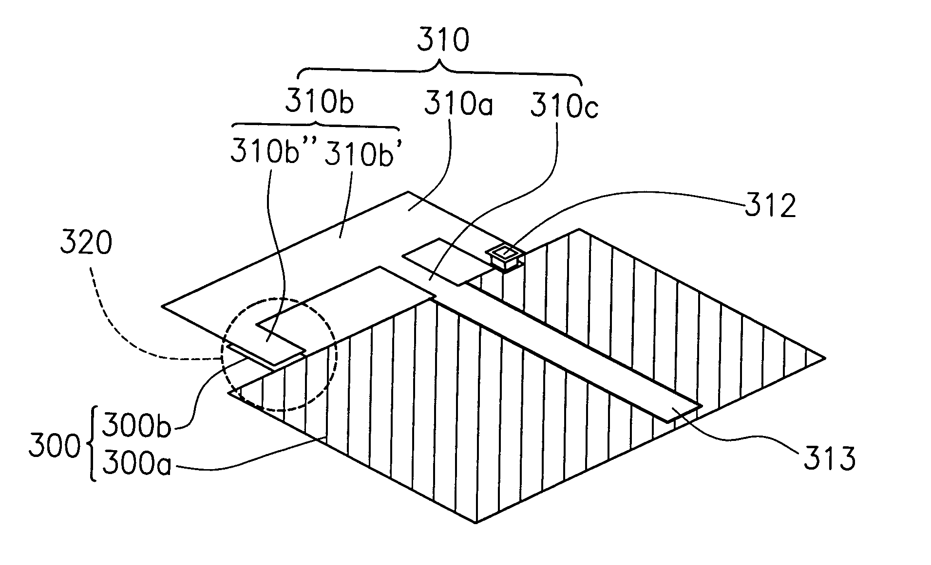
[0012]The invention provides an antenna with a printed compensating capacitor. As a result, the length of tuning section of the antenna can be reduced but keeping the required LC coupling effect.
[0014]The invention provides an printed antenna, in which the antenna is formed on the PCB. The fabrication process of the antenna is compatible for the processes to form the electronic elements on the PCB. The mechanical strength of the antenna is improved. The antenna is directly formed on the PCB, so as to have the better compact assembly.

Problems solved by technology

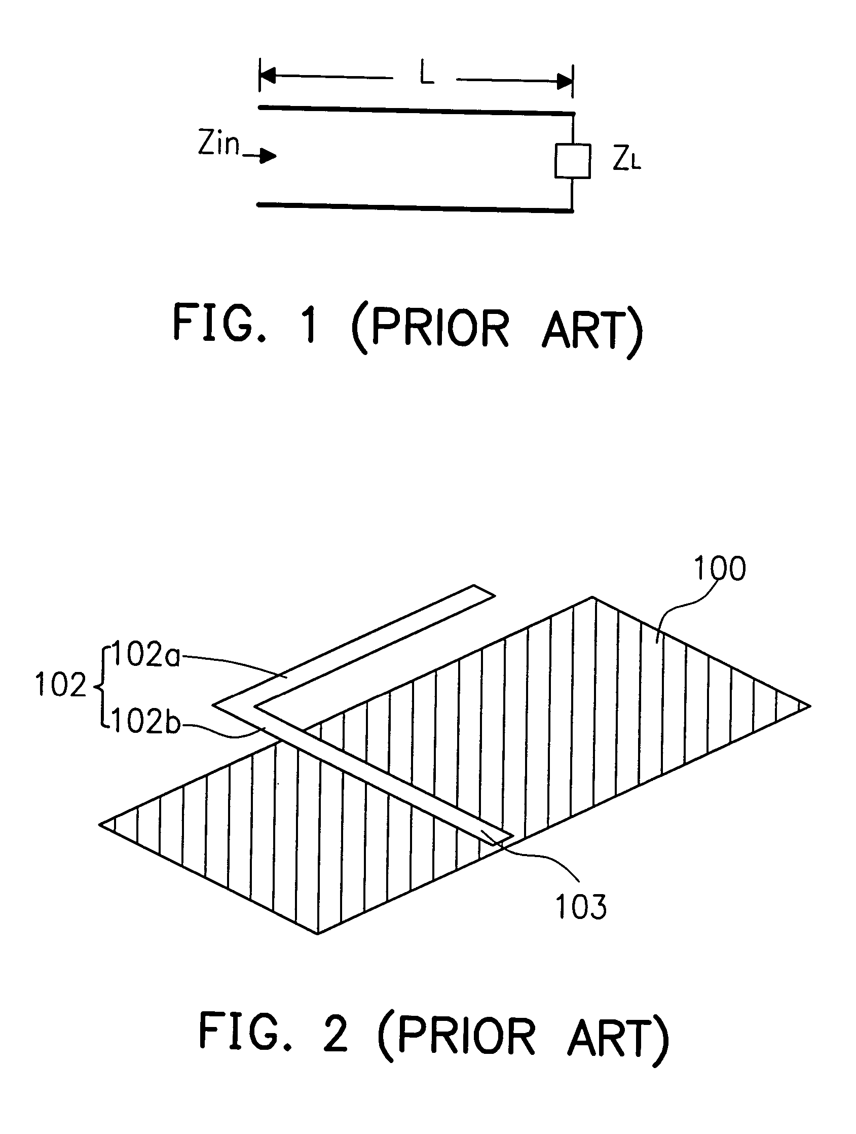
However, these conventional antennas are not implemented on the plane of a printed circuit board (PCB).
This is not a compact design, and needs additional fabrication process.

Method used


Image

  • Antenna with printed compensating capacitor
  • Antenna with printed compensating capacitor
  • Antenna with printed compensating capacitor

Examples


Embodiment Construction

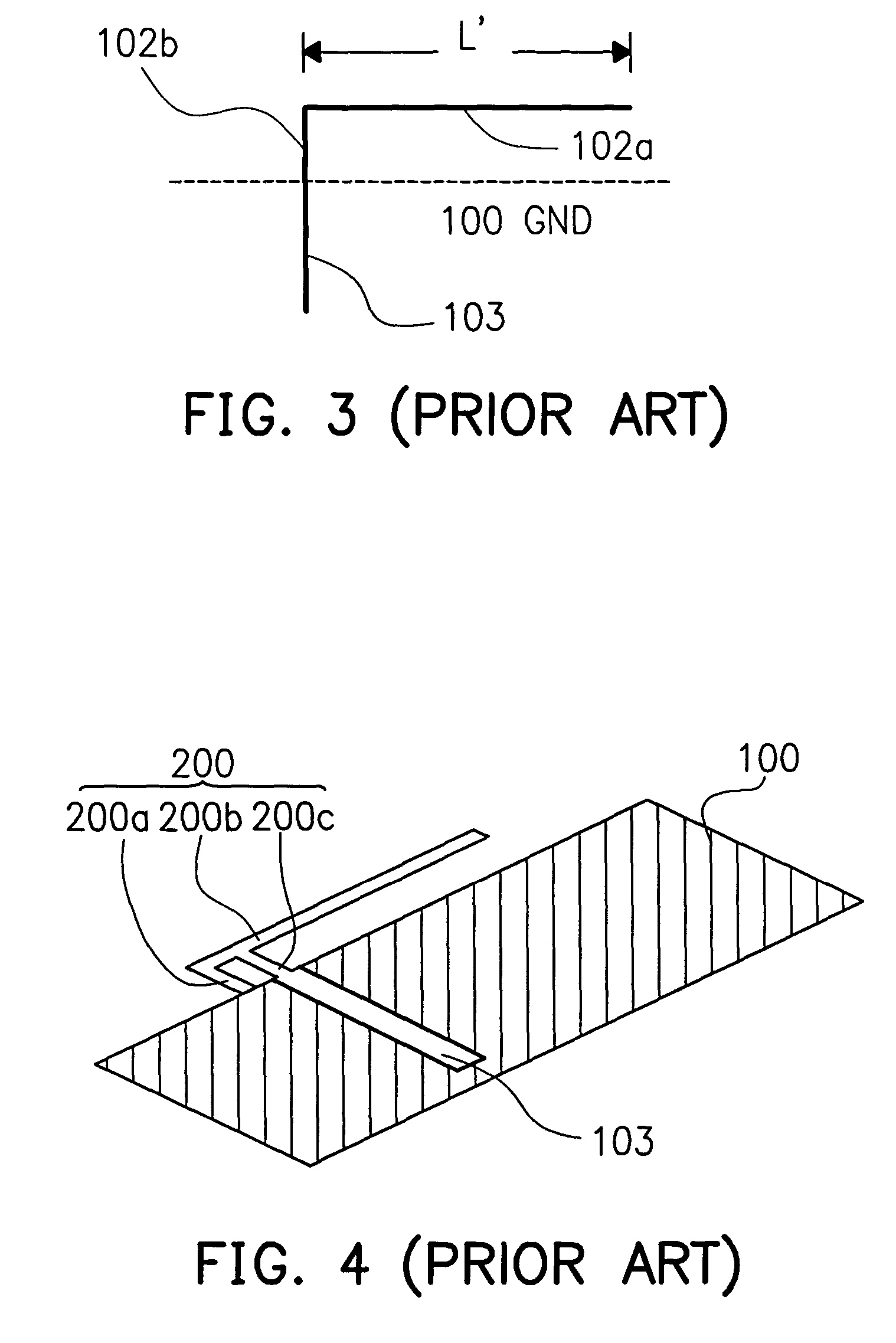
[0029]According to the microstrip line theory, the tuning section and the short circuit stub section have different characteristics by their respective length Lo and Ls, as shown in FIG. 5. Referring back to FIG. 5, the short circuit stub section 200a provides the inductive effect and the tuning section 200b is a capacitive element when their length Lo and Ls are respectively smaller than quarter wavelength. Actually, the radiator, such as an inverted F antenna, includes a short circuit stub section and a tuning section.

[0030]Since the tuning section 200b needs the length near 1 / 4 wavelength, the radiator of the inverted F antenna spends much space for tracing out. This causes the size of antenna to be large.

[0031]One issue investigated in the invention is as follows. Given the equivalent capacity from feeding point forward the tuning section as CF in inverted F antenna, an external or distributed capacitor may be used being electrically coupled between the tuning section and the gr...


PUM


Abstract

An antenna on a printed circuit board (PCB) with a compensating capacitor. The antenna has a radiator disposed over a first surface of the PCB. Wherein the radiator includes a signal feeding section and a tuning section coupled together at a joint. The tuning section includes a bending portion. Also and, a ground layer with or without a protuding portion is disposed on a second surface of the PCB, wherein the bending portion of the tuning section is overlapping with the ground layer to form the compensating capacitor. In addition, the radiator can also have a short circuit stub section, electrically coupled to the ground layer.

Description

CROSS-REFERENCE TO RELATED APPLICATION[0001]This application claims the priority benefits of U.S. provisional application titled “MINIATURING PRINTED ANTENNA WITH LOAD PRINTED CAPACITOR” filed on May 15, 2003, Ser. No. 60 / 470,906. All disclosure of this application is incorporated herein by reference.BACKGROUND OF THE INVENTION[0002]1. Field of Invention[0003]The present invention relates to a communication antenna. More particularly, the present invention relates to an antenna with an additional capacitor, so as to reduce the dimension of the antenna and maintain the required LC coupling strength.[0004]2. Description of Related Art[0005]The wireless communication system always needs an antenna to transmit and receive RF signals. In recent years, the wireless communication technology has been well developed. For example, the cellular phone is one of the impressing apparatus in wireless communication. The dimension of the cellular phone require an antenna. In order to implement the a...

Claims


Application Information

Patent Timeline
IPC IPC(8): H01Q1/38H01Q1/24H01Q9/04H01Q9/42
CPCH01Q1/243H01Q9/42H01Q9/0442H01Q9/0421
Inventor CHEN, KAI-TELEENG, JAN-KWOLIN, TSUNG-LIANG
Owner MEDIATEK INC
Learn More