Robot, control apparatus, and robot system

a control apparatus and robot technology, applied in the field of robots, can solve the problems of easy link vibration, difficult oscillation, and easy oscillation of robots

Active Publication Date: 2017-02-02
SEIKO EPSON CORP
View PDF2 Cites 6 Cited by
  • Summary
  • Abstract
  • Description
  • Claims
  • Application Information

AI Technical Summary

Benefits of technology

[0011]An advantage of some aspects of the invention is to solve at least a part of the problems described above, and the invention can be implemented as the following aspects or application examples.

Problems solved by technology

Accordingly, there is a problem that vibration is easily caused in the links due to rotation of the links, disturbance on the links, or the like.
First, in the robot, when the arm is extended, the moment of inertia is larger and the vibration is larger, and, when the arm is folded, the moment of inertia is smaller and the vibration is smaller.
Further, when the arm is extended, the robot is harder to oscillate even when the feedback gain is raised, however, when the arm is folded, the robot is easier to oscillate.
Accordingly, in single fixed feedback gain, a vibration suppression effect may not sufficiently be obtained or oscillation is easily caused.
As described above, in the robot of related art, it is impossible to sufficiently suppress the vibration.

Method used


Image

  • Robot, control apparatus, and robot system
  • Robot, control apparatus, and robot system
  • Robot, control apparatus, and robot system

Examples


Embodiment Construction

[0050]As below, a robot, a control apparatus, and a robot system according to the invention will be explained in detail based on an embodiment shown in the accompanying drawings.

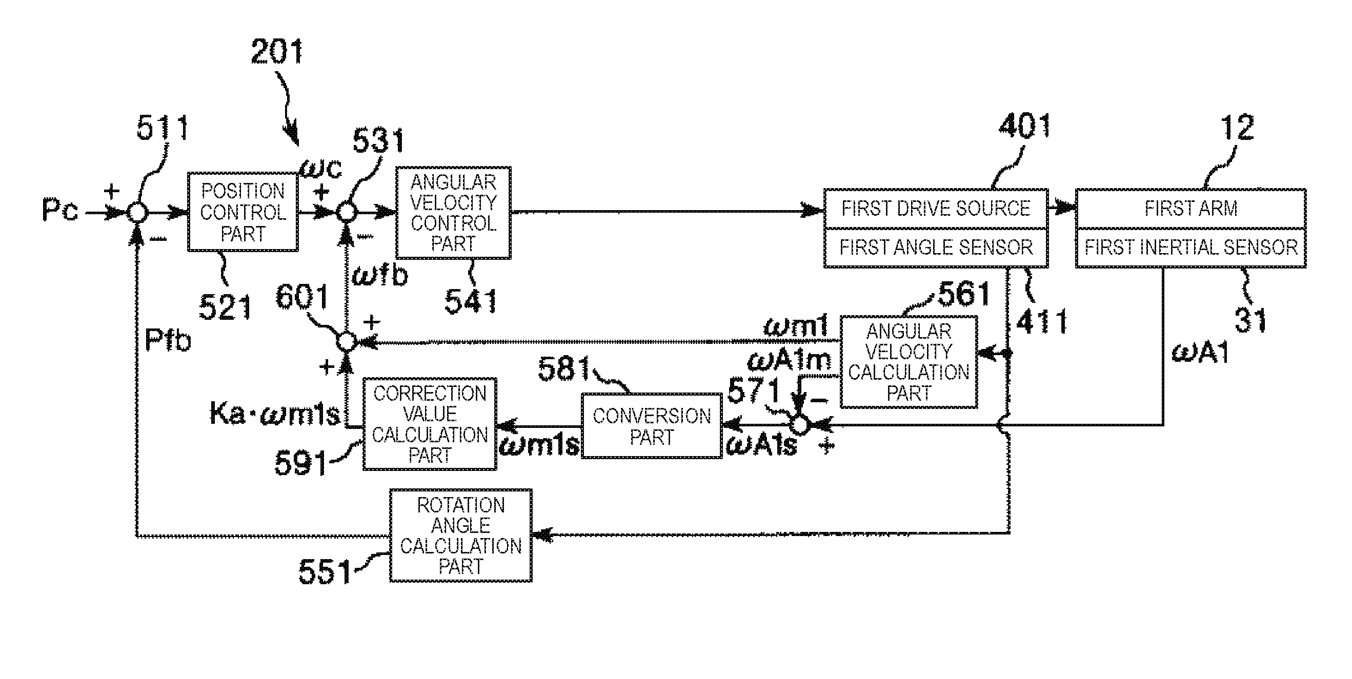
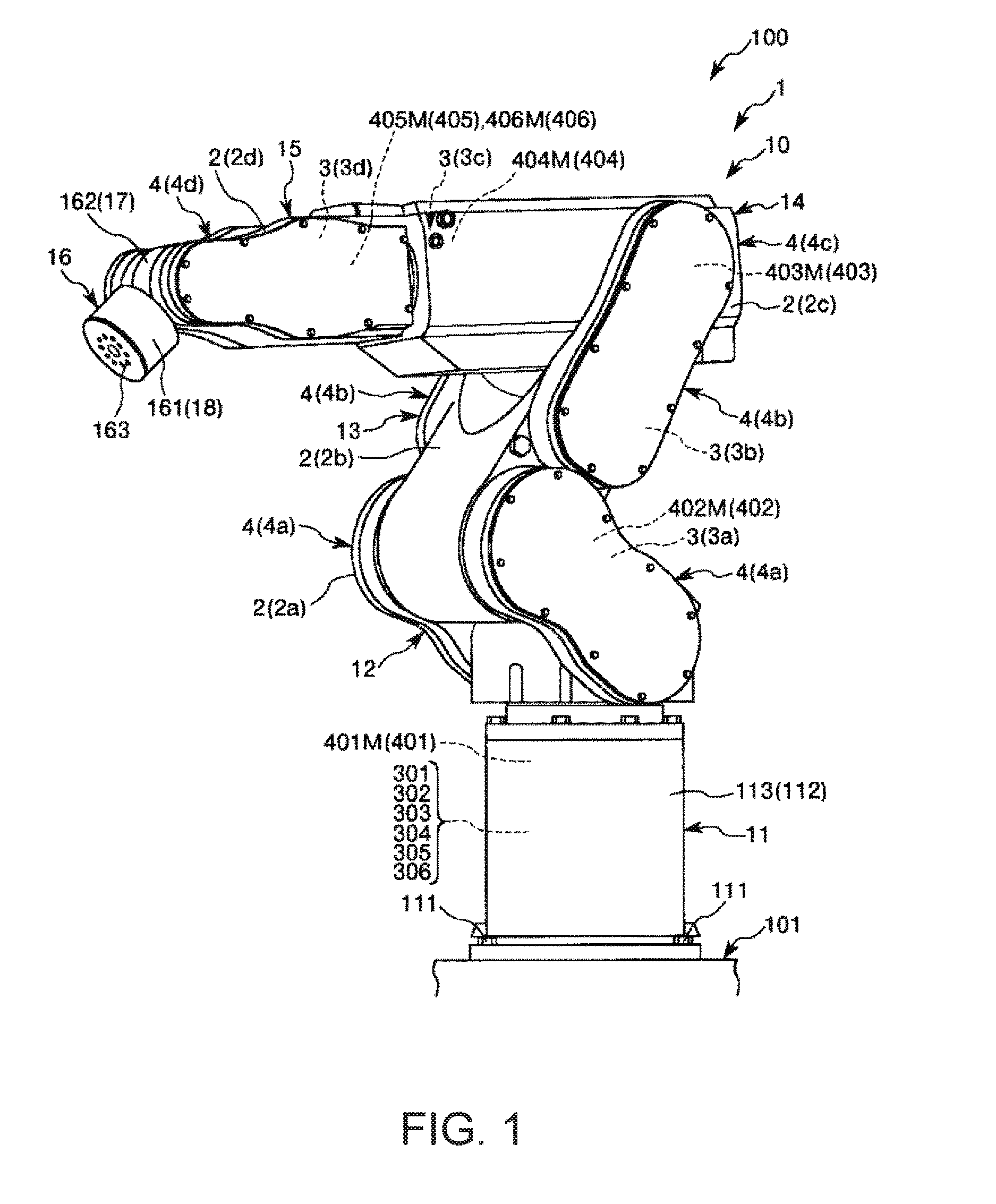
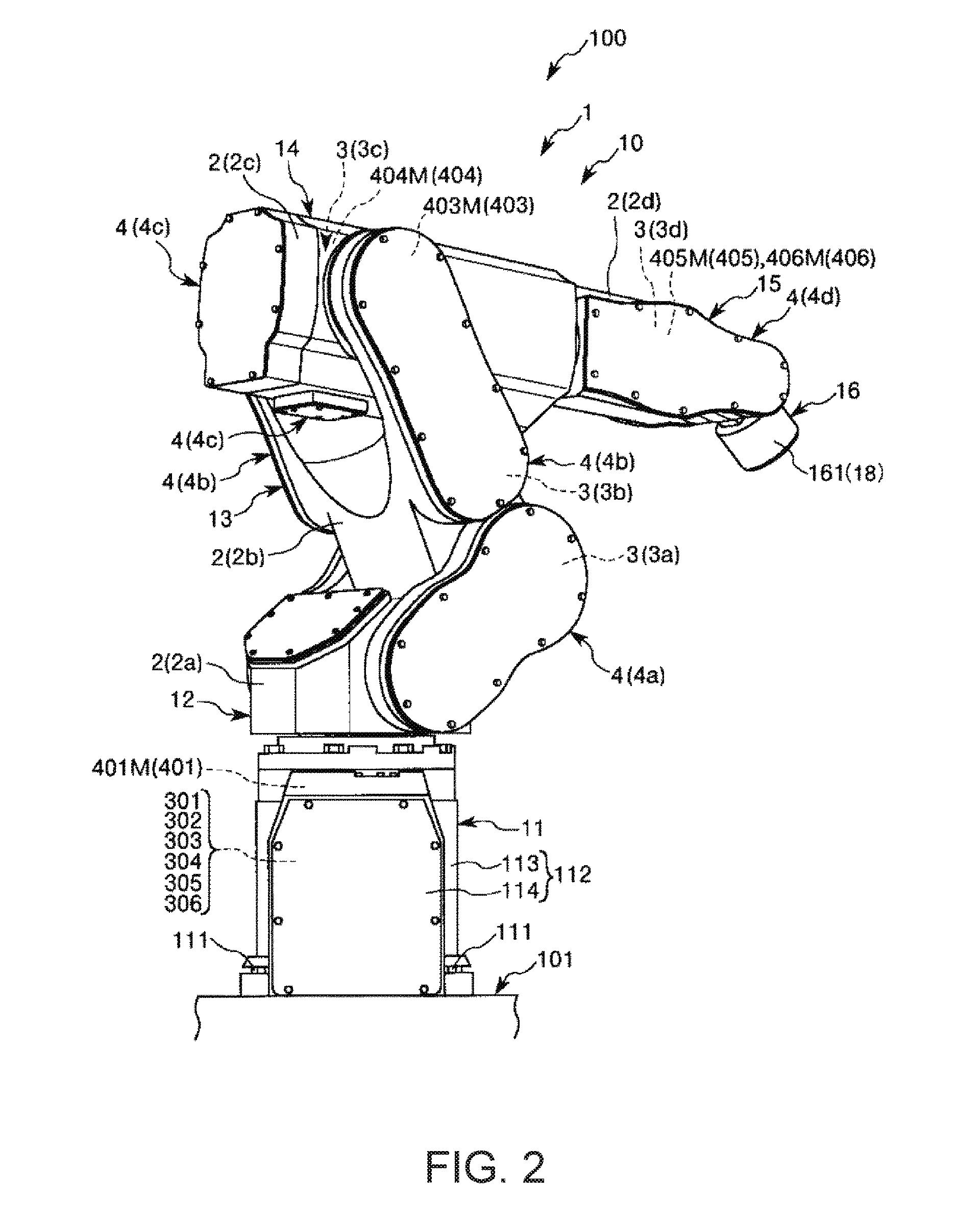
[0051]FIG. 1 is a perspective view of an embodiment of a robot of a robot system according to the invention as seen from a front side. FIG. 2 is a perspective view of the robot of the robot system shown in FIG. 1 as seen from a back side. FIGS. 3 to 6 are respectively schematic diagrams of the robot of the robot system shown in FIG. 1. FIGS. 7 to 12 are respectively block diagrams of main parts of the robot system shown in FIG. 1. FIGS. 13 to 15 are respectively graphs showing configuration examples of calibration curves of the robot system shown in FIG. 1.

[0052]Note that, hereinafter, for convenience of explanation, the upside in FIGS. 1 to 6 is referred to as “up” or “upper” and the downside is referred to as “down” or “lower”. Further, the base side in FIGS. 1 to 6 is referred to as “proximal end” and the...


PUM


Abstract

A robot includes a robot arm and an inertial sensor provided in the robot arm. The robot arm is controlled using a weighting value for weighting output from the inertial sensor. In at least apart of a range in which the robot arm is movable, the weighting value is a first value when acceleration of the robot arm is first acceleration, and changes from the first value to a second value higher than the first value when the acceleration of the robot arm changes from the first acceleration to second acceleration lower than the first acceleration.

Description

BACKGROUND[0001]1. Technical Field[0002]The present invention relates to a robot, a control apparatus, and a robot system.[0003]2. Related Art[0004]In related art, a robot including a pedestal (base) and a plurality of links (arms) has been known (for example, see Patent Document 1 (JP-A-2005-242794)). One link of the two adjacent links is rotatably coupled to the other link via a joint part, and the link closest to the base is rotatably coupled to the pedestal via a joint part.[0005]In the robot, the joint part for coupling the pedestal and the link and the joint part for coupling the links have lower rigidity than the base and the links due to influences of their spring elements. Accordingly, there is a problem that vibration is easily caused in the links due to rotation of the links, disturbance on the links, or the like.[0006]In the robot disclosed in Patent Document 1, angular velocity sensors are provided in the links and motors for rotating the links are feedback-controlled u...

Claims


Application Information

Patent Timeline
Patent Type & Authority Applications(United States)
IPC IPC(8): B25J9/16B25J13/08
CPCB25J9/1638B25J13/088B25J9/1694G05B2219/39195Y10S901/46G05B2219/40597B25J9/1651G05B2219/37134G05B2219/37388G05B2219/41021G05B2219/41025
Inventor GOMI, AKIHIROTOSHIMITSU, SHUNSUKE
Owner SEIKO EPSON CORP
Why Eureka
Try Eureka