Obstacle determining apparatus, moving body, and obstacle determining method

a technology of obstacle detection and apparatus, applied in the direction of process and machine control, using reradiation, instruments, etc., can solve the problems of difficult to detect the ground and obstacle while distinguishing, difficult to detect the ground and obstacle to be detected, and difficult to perform accurate discrimination

Active Publication Date: 2017-02-02
SHARP KK
View PDF0 Cites 14 Cited by
  • Summary
  • Abstract
  • Description
  • Claims
  • Application Information

AI Technical Summary

Benefits of technology

[0033]According to the invention, in an obstacle determining apparatus including a distance measuring device, without a complicated configuration or algorithm, simple algorithm makes it possible to prevent a ground from being erroneously detected as an obstacle even when shaking due to an impact is generated or when there is concave and convex of the ground or a change in inclination of the ground, by defining or changing a measurement space region in front of the distance measuring device so that the ground is difficult to be detected.

Problems solved by technology

With a configuration in which an obstacle is detected by using a distance measuring device, it is possible to measure a distance to an object by the distance measuring device, but when a ground is included in a measurement range (measurement space region) by the distance measuring device, it is difficult to detect the ground and an obstacle to be detected while distinguishing them.
Even when setting is performed so that the measurement space region does not include the ground in order to solve such a problem, the ground appears in the measurement space region when a vehicle body and the distance measuring device shake or at a position where concave and convex on the ground exist or inclination of the ground changes, resulting that it is difficult to detect the ground and the obstacle to be detected while distinguishing them.
However, even with such a method, the relative angle between the distance measuring device and the ground varies when the vehicle body and the distance measuring device shake or at a position where inclination of the ground changes, so that it is difficult to perform accurate discrimination.
In this case, however, load of the data processing increases.
Further, when shaking due to an impact or a change in the inclination of the ground is corrected by the data processing, algorithm becomes more complicated and the load of the data processing further increases.
Thus, a high-performance and high-cost processing system is required to perform the data processing with a large load.

Method used


Image

  • Obstacle determining apparatus, moving body, and obstacle determining method
  • Obstacle determining apparatus, moving body, and obstacle determining method
  • Obstacle determining apparatus, moving body, and obstacle determining method

Examples


first embodiment

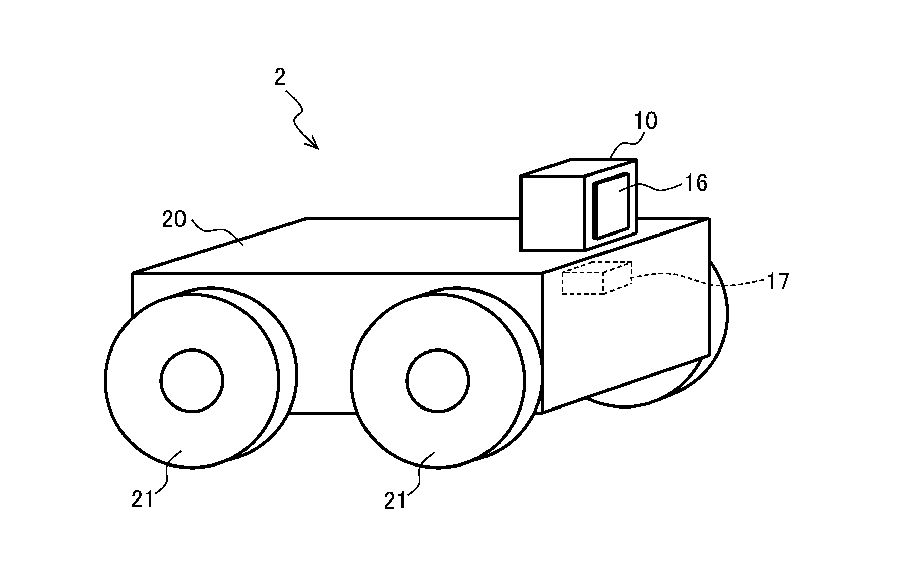
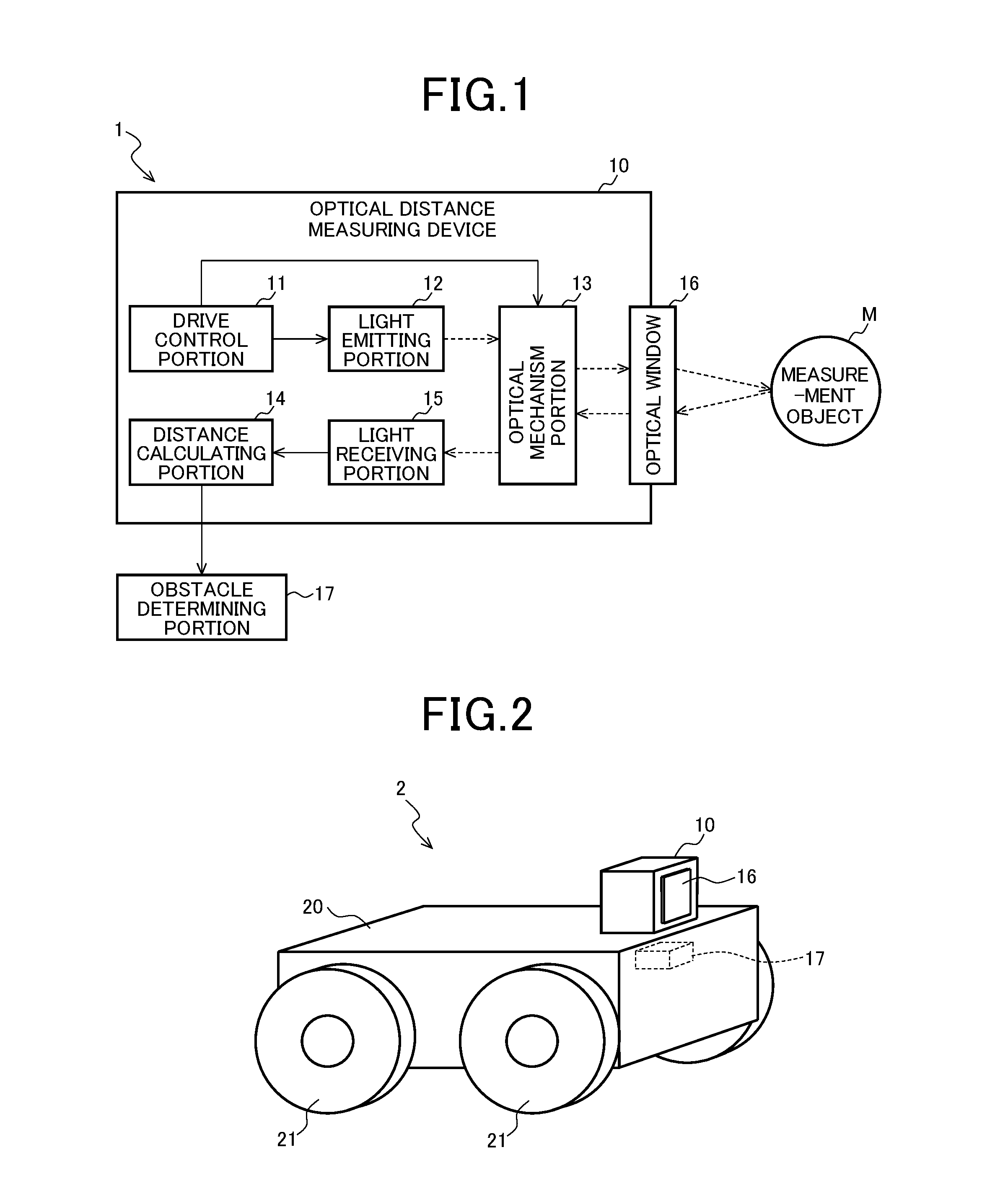
[0068]A first embodiment of the invention will be described with reference to FIG. 1 to FIG. 4C. FIG. 1 is a block diagram illustrating one configuration example of an obstacle determining apparatus according the present embodiment. FIG. 2 is an external view illustrating one configuration example of a moving body including the obstacle determining apparatus of FIG. 1.

[0069]As exemplified in FIG. 1, an obstacle determining apparatus 1 according to the present embodiment includes an optical distance measuring device (hereinafter, simply referred to as a distance measuring device) 10 which measures a distance to a measurement object M by an optical measuring mechanism, and an obstacle determining portion 17.

[0070]Specifically, the distance measuring device 10 modulates measurement light output from a laser light source, radiates the resultant to the object through an optical window, and detects reflection light from the measurement object M by a light receiving element through the opt...

second embodiment

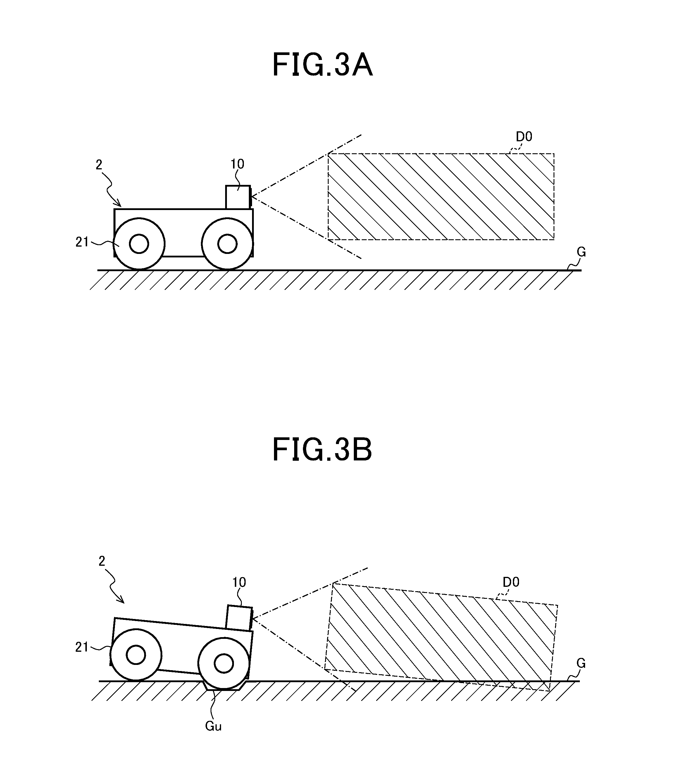
[0094]A second embodiment of the invention will be described with reference to FIG. 5A and FIG. 5B. FIG. 5A is a cross-sectional view of a plane vertical to an advancing direction for illustrating an example of a measurement space region of a moving body provided with an obstacle determining apparatus according to the second embodiment of the invention, and FIG. 5B is a schematic view illustrating an example in which the measurement space region of FIG. 5A changes due to a topographic change. Note that, in the present embodiment, though description for overlapping parts with the first embodiment will be basically omitted, various applications described in the first embodiment are able to be applied.

[0095]In the first embodiment, as exemplified with the measurement space region D1, a measurement space region is defined so that a position of a bottom surface thereof becomes higher stepwisely or continuously according to a depth in a forward direction thereof. On the other hand, in the...

third embodiment

[0100]As described above, applications of the first embodiment are able to be applied to the second embodiment. As a third embodiment of the invention, an embodiment to which both of the embodiments are applied will be described with reference to FIG. 6. FIG. 6 is a perspective view illustrating one example of a measurement space region of a moving body provided with an obstacle determining apparatus according to the present embodiment. Note that, in the present embodiment, though description for overlapping parts with the first and second embodiments will be basically omitted, various applications described in the first and second embodiments are able to be applied.

[0101]In the present embodiment, both of the first and second embodiments are applied and a measurement space region is defined so that a position of a bottom surface thereof becomes higher stepwisely or continuously according to a depth in a forward direction thereof and a depth in a lateral direction (width direction) ...


PUM


Abstract

An obstacle determining apparatus includes a distance measuring device, and an obstacle determining portion which determines presence / absence of an obstacle in a measurement space region in front of the distance measuring device. The measurement space region is defined so that a position of a bottom surface of the measurement space region changes stepwisely or continuously according to a depth in a forward direction and / or a width direction of the measurement space region, for example, like a measurement space region D1. The measurement space region may be changed so that the position of the bottom surface of the measurement space region changes stepwisely or continuously according to a detection result of an inclination detecting portion.

Description

CROSS-NOTING PARAGRAPH[0001]This non-provisional application claims priorities under 35 U.S.C. §119(a) on Patent Applications No. 2015-147358 filed in JAPAN on Jul. 27, 2015 and No. 2015-185415 filed in JAPAN on Sep. 18, 2015, the entire contents of which are hereby incorporated herein by reference.FIELD OF THE INVENTION[0002]The present invention relates to an obstacle determining apparatus, a moving body, and an obstacle determining method.BACKGROUND OF THE INVENTION[0003]An autonomous traveling apparatus (also referred to as an automatic traveling apparatus) that determines its own operation by using sensor information and acts autonomously has been developed. For example, an optical distance measuring device (distance measuring sensor) is able to measure a distance to an object present in a measurement range and obtain a one-dimensional or two-dimensional distance data map, and is thus used as a safety device which is used for the autonomous traveling apparatus to detect and avo...

Claims


Application Information

Patent Timeline
Patent Type & Authority Applications(United States)
IPC IPC(8): B60W30/09G01S17/08G01S17/93G01S17/02G01S17/04G01S17/10G01S17/86G01S17/894G01S17/931
CPCB60W30/09G01S17/026G01S17/08B60W2900/00B60W2550/10B60W2720/10G01S17/936G01S17/10G01S17/36G01S17/42G01S7/497G01S17/04G01S17/86G01S17/931G01S17/894G05D1/024B60W2554/00
Inventor KURODA, TATSURO
Owner SHARP KK
Why Eureka
Try Eureka