Cable guide for wire basket cable tray

a cable tray and wire basket technology, applied in the direction of electrical appliances, instruments, optics, etc., can solve the problems of cable tangles, difficult cable installation, snapping or damaging cables,

Active Publication Date: 2017-02-02
EATON INTELLIGENT POWER LTD
View PDF1 Cites 1 Cited by
  • Summary
  • Abstract
  • Description
  • Claims
  • Application Information

AI Technical Summary

Problems solved by technology

Corners or turns along the cable route or pathway defined by the cable trays make installation of cables difficult.
More specifically, a cable must be carefully guided by hand around corners and turns during installation as there is a risk of snapping or damaging the cable against the sides or edges of the wire basket cable trays that form the corner of the turn or surrounding support brackets or hangers.
The cables may also become tangled if not kept aligned with the route of the trays.

Method used


Image

  • Cable guide for wire basket cable tray
  • Cable guide for wire basket cable tray
  • Cable guide for wire basket cable tray

Examples


Embodiment Construction

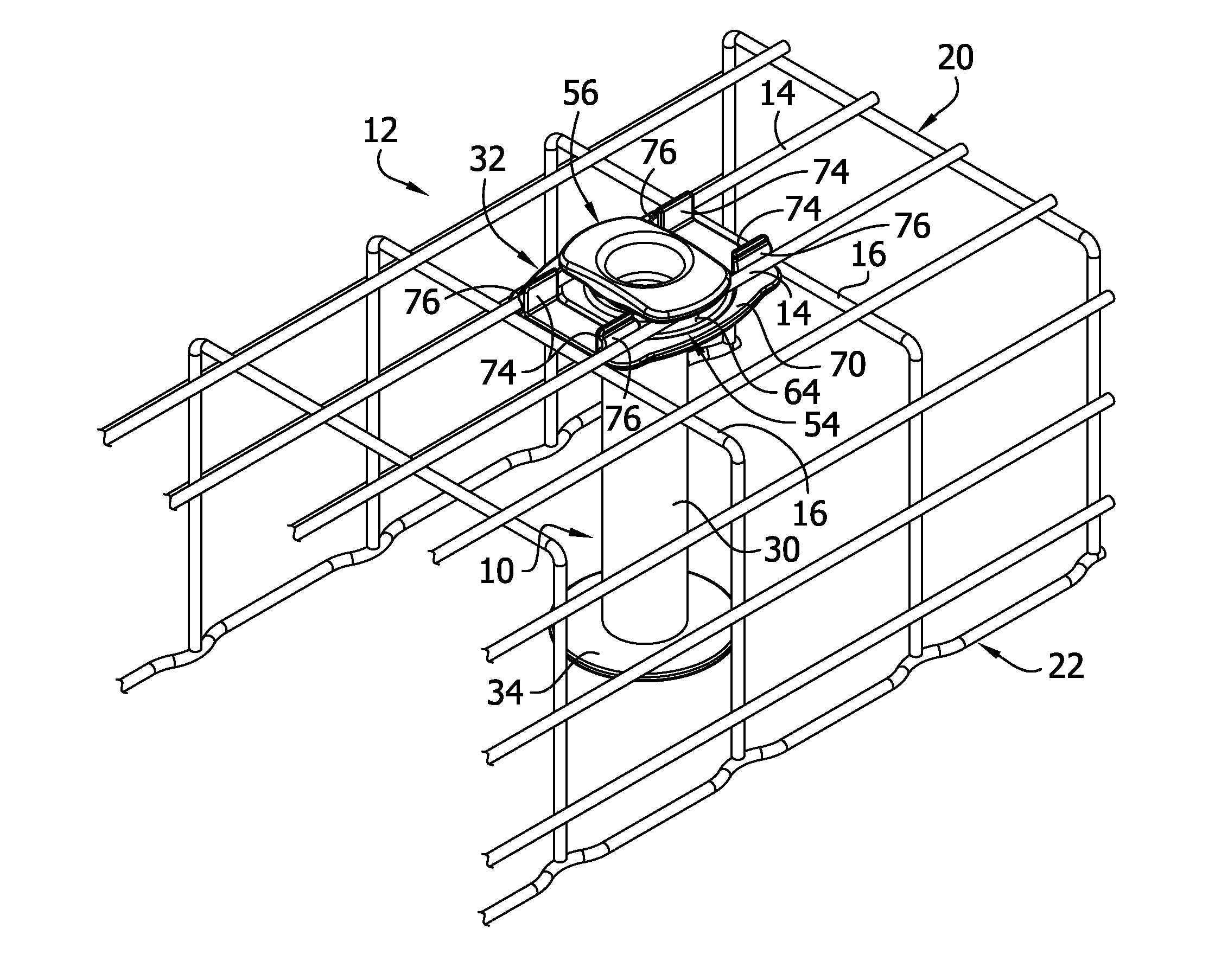
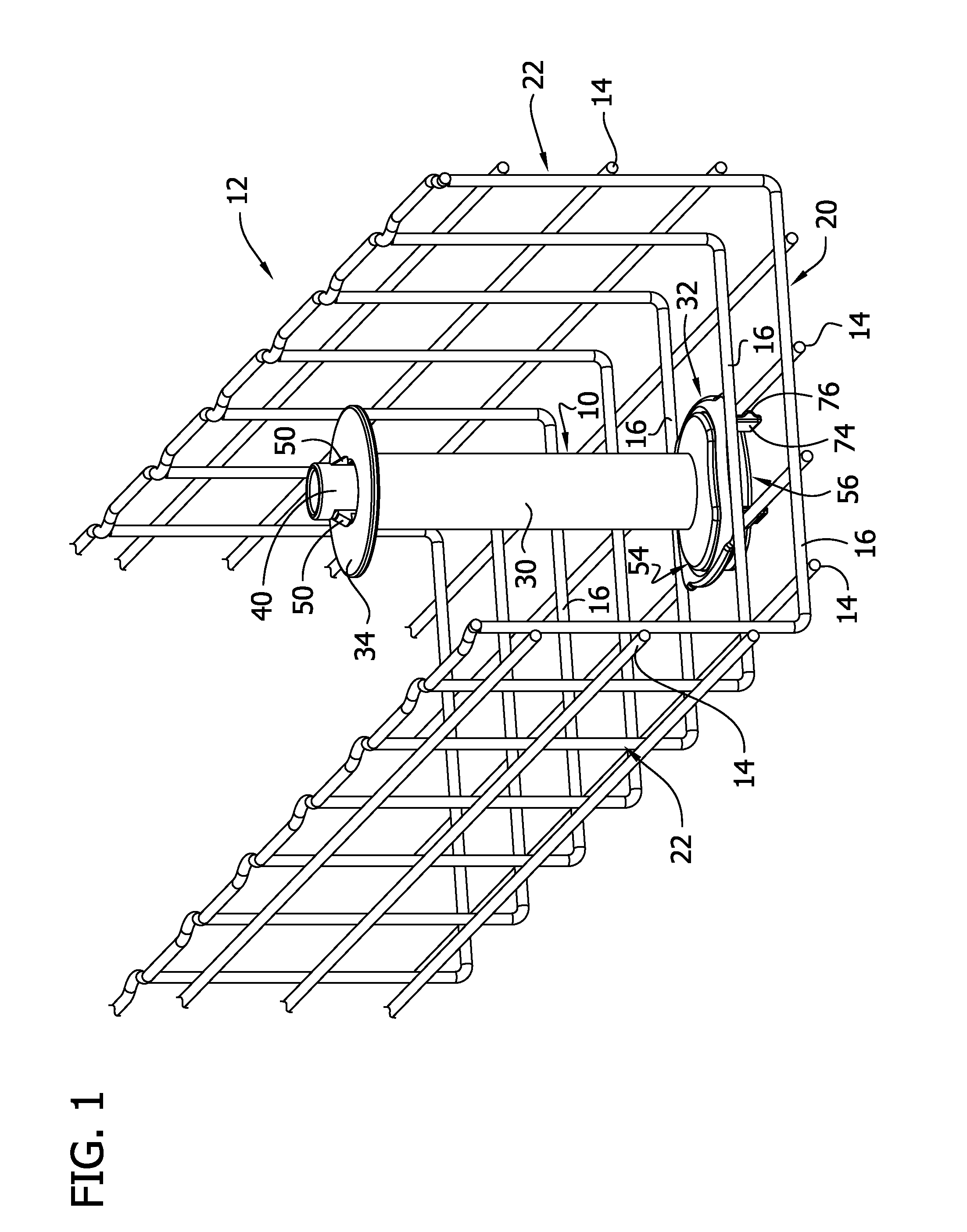
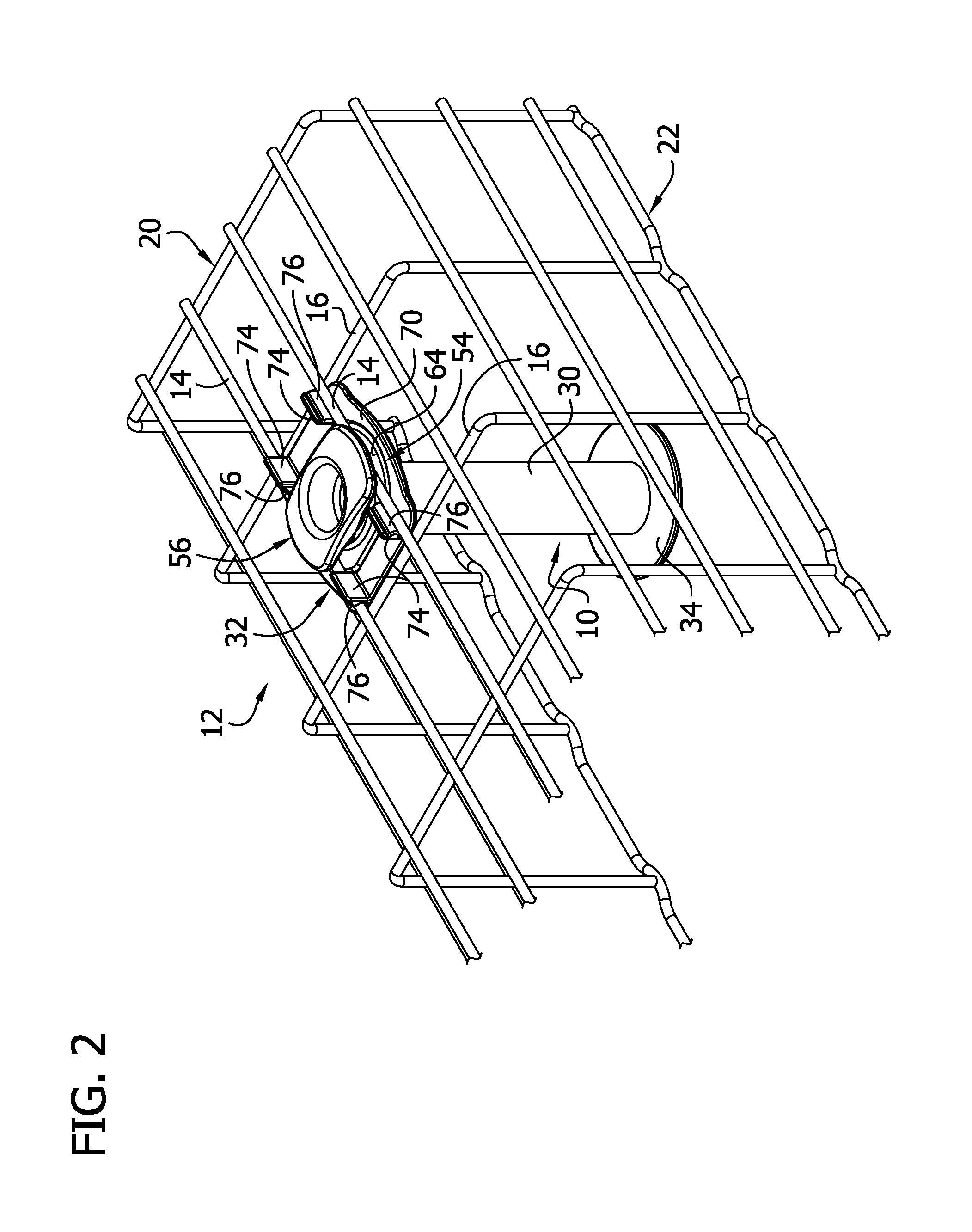
[0021]Referring to FIGS. 1 and 2 of the drawings, a cable guide, generally indicated at reference numeral 10, is attached to a wire basket cable tray, generally indicated at reference numeral 12. The cable guide 10 is used to guide cables or wires (not shown) along the wire basket cable tray 12, particularly around corners or other bends along the run of the cable tray. As explained in more detail below, the cable guide 10 is readily attachable to the wire basket cable tray 12 without the use of additional tools or fasteners.

[0022]Referring to FIG. 3, the wire basket cable tray 12 includes a plurality of longitudinal wires 14 extending along a length of the cable tray, and a plurality of transverse wires 16 secured to the longitudinal wires and extending generally transverse to the longitudinal wires. In the illustrated embodiment, the transverse wires 16 are secured on upper portions of the longitudinal wires 14, although the transverse wires may be secured to the lower portions of...


PUM


Abstract

A guide body for a cable guide includes a stem having an upper end, a lower end, and a longitudinal axis extending between the upper and lower ends, and base adjacent the lower end of the stem. The guide body is rotatable about the longitudinal axis of the stem to configure the base from an unlocked orientation relative to the wire basket cable tray, in which the base is receivable in and removable from a floor opening of a wire basket cable tray, and a locked orientation relative to the wire basket cable tray, in which the base is secured to the wire basket cable tray in the floor opening. A snap-fit component attaches a roller retainer to a stem body by snap-fit connection when a roller is received on the stem body to retain the roller on the stem body.

Description

FIELD OF THE DISCLOSURE[0001]The present disclosure generally relates to a cable guide for a wire basket cable tray.BACKGROUND OF THE DISCLOSURE[0002]Cable support systems featuring trays are known for supporting a network of cables below raised floors or above hung ceilings and in other areas where cable networks are located. The conventional cable tray system is made up of a large number of trays positioned end to end along a desired route where cables are to be placed and supported. The cable trays, in turn, are supported by a number of brackets or hangers mounted on support shafts (such as sub-floor support shafts holding up a raised floor), walls, ceilings, floors or other building structures. The trays are connected to each other by clips or clamps. One type of cable tray is a wire basket cable tray. The wire basket cable tray comprises a plurality of spaced apart longitudinal wires secured (e.g., welded) to a plurality of spaced apart transverse wires.[0003]Corners or turns a...

Claims


Application Information

Patent Timeline
Patent Type & Authority Applications(United States)
IPC IPC(8): F16L3/26F16L3/06F16L3/22
CPCF16L3/26F16L3/06F16L3/22H02G3/0443G02B6/4459H02G1/08H02G3/0406G02B6/475
Inventor THOMPSON, STEPHEN NATHANIELSHELTON, TRAVIS COLERAVILLA, MOHAN
Owner EATON INTELLIGENT POWER LTD
Why Eureka
Try Eureka