
Counter-flow heat exchanger with helical passages

a technology of helical passages and heat exchangers, which is applied in the direction of indirect heat exchangers, lighting and heating apparatus, tubular elements, etc., can solve the problems of affecting the manufacture of tube bundles of this type, the assembly of tube bundles with contiguous helical tubes and their connection becoming particularly problematic, and the connection and formation of numerous problems of conventional heat exchangers

Active Publication Date: 2017-02-02
GENERAL ELECTRIC CO
View PDF7 Cites 41 Cited by
  • Summary
  • Abstract
  • Description
  • Claims
  • Application Information

AI Technical Summary

Benefits of technology

The invention has certain benefits and advantages that are explained in parts of the description. However, the technical effects of the invention can be easily identified by practicing it.

Problems solved by technology

Conventional heat exchangers with a plurality of tubes have drawbacks with regard to the connection and formation of numerous inaccessible tubes with small spacing.
However, the assembly of tube bundles with contiguous helical tubes and their connection become particularly problematic as the number of tubes increases and were hitherto at best possible with a very small number of helical tubes.
As already mentioned, the manufacture of tube bundles of this type becomes particularly problematic when the number of tubes is increased inasmuch as the connection of the contiguous tubes becomes particularly difficult due to the inaccessibility of the tube ends and therefore is not possible with conventional connecting means.
It is further particularly difficult to bend rigid tubes into exactly contiguous coils and to connect them by conventional connecting means.

Method used


Image

  • Counter-flow heat exchanger with helical passages
  • Counter-flow heat exchanger with helical passages
  • Counter-flow heat exchanger with helical passages

Examples


Embodiment Construction

[0017]Reference now will be made in detail to embodiments of the invention, one or more examples of which are illustrated in the drawings. Each example is provided by way of explanation of the invention, not limitation of the invention. In fact, it will be apparent to those skilled in the art that various modifications and variations can be made in the present invention without departing from the scope or spirit of the invention. For instance, features illustrated or described as part of one embodiment can be used with another embodiment to yield a still further embodiment. Thus, it is intended that the present invention covers such modifications and variations as come within the scope of the appended claims and their equivalents.

[0018]As used herein, the terms “first”, “second”, and “third” may be used interchangeably to distinguish one component from another and are not intended to signify location or importance of the individual components.

[0019]The terms “upstream” and “downstre...


PUM


Abstract

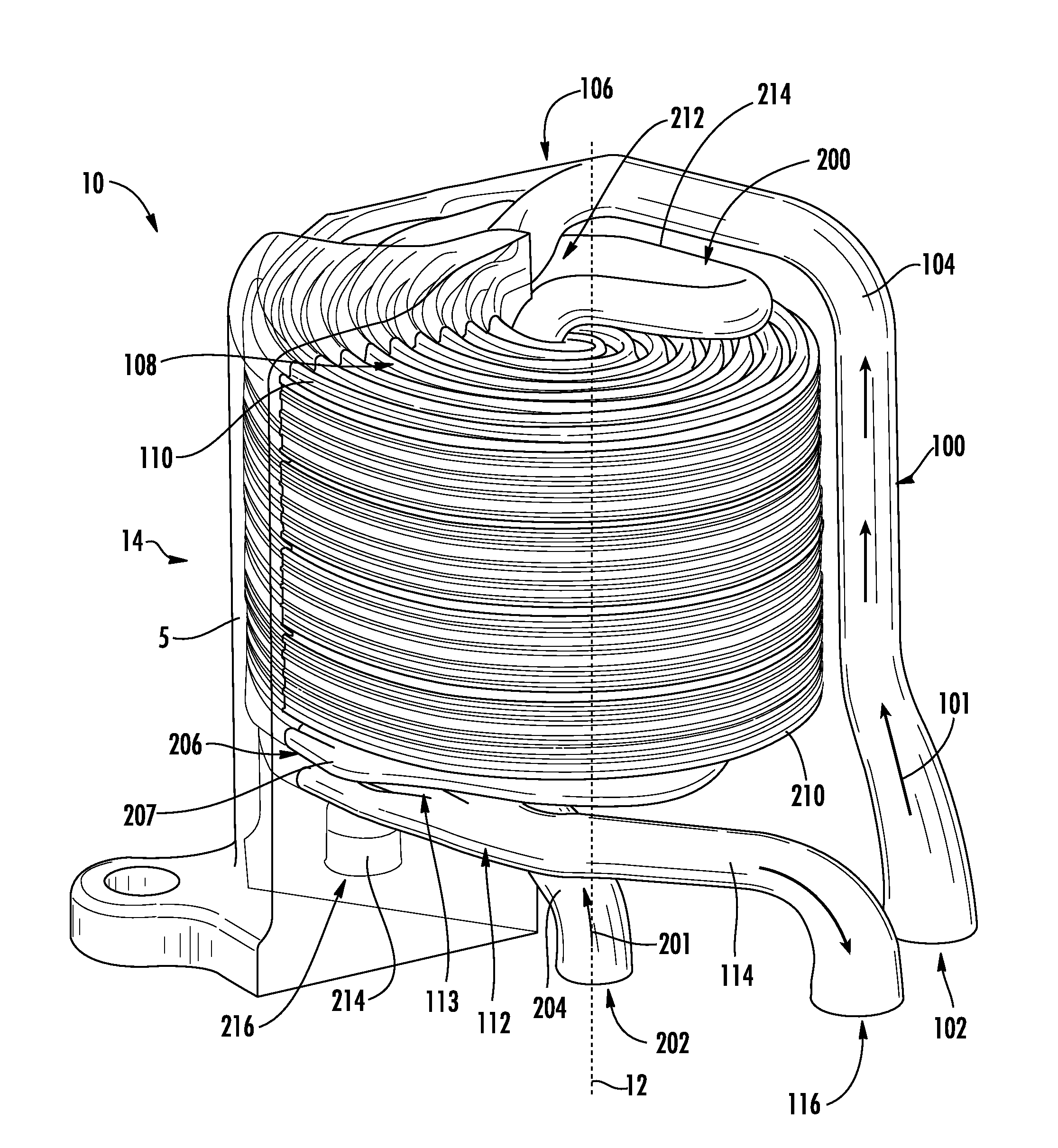
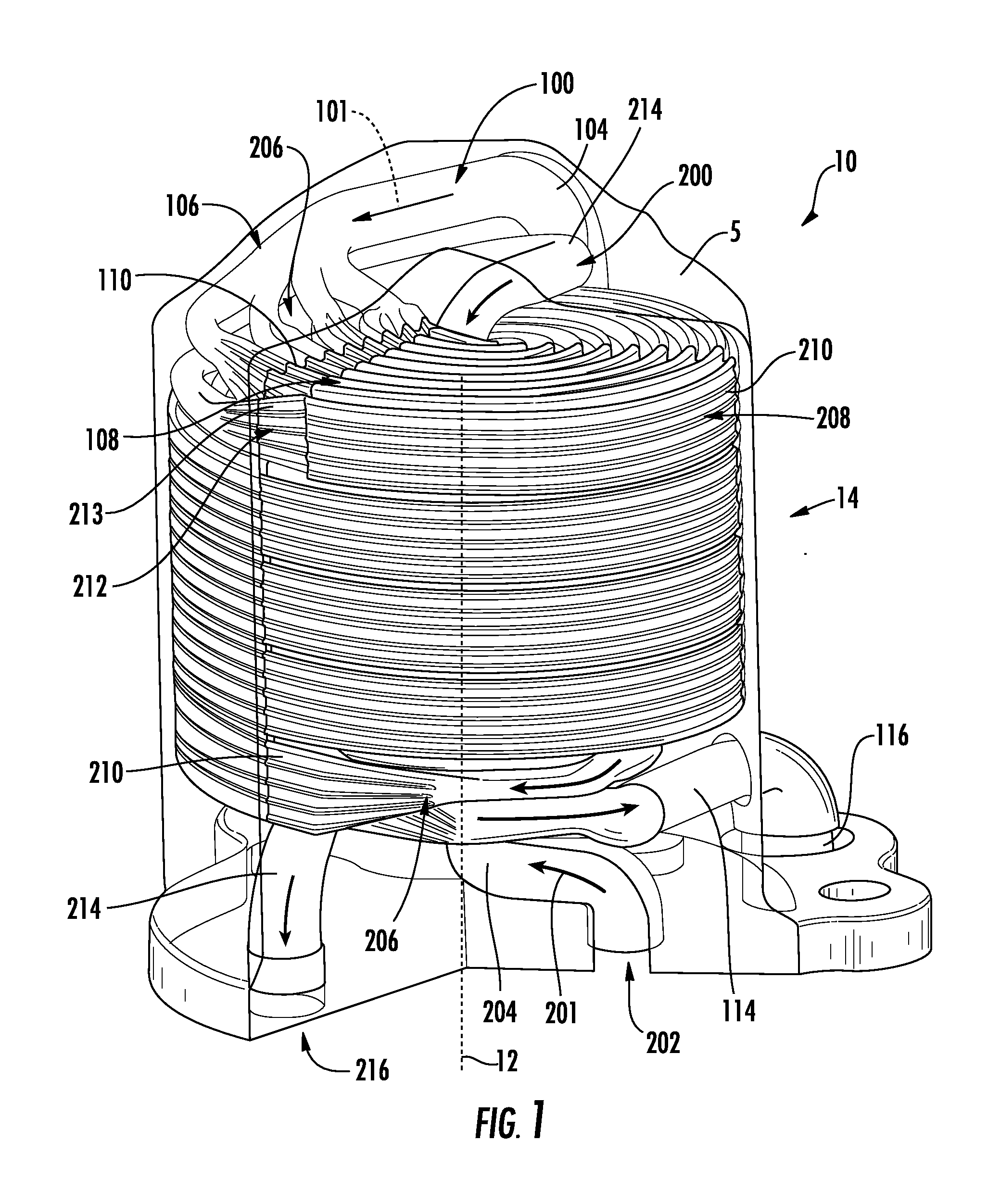
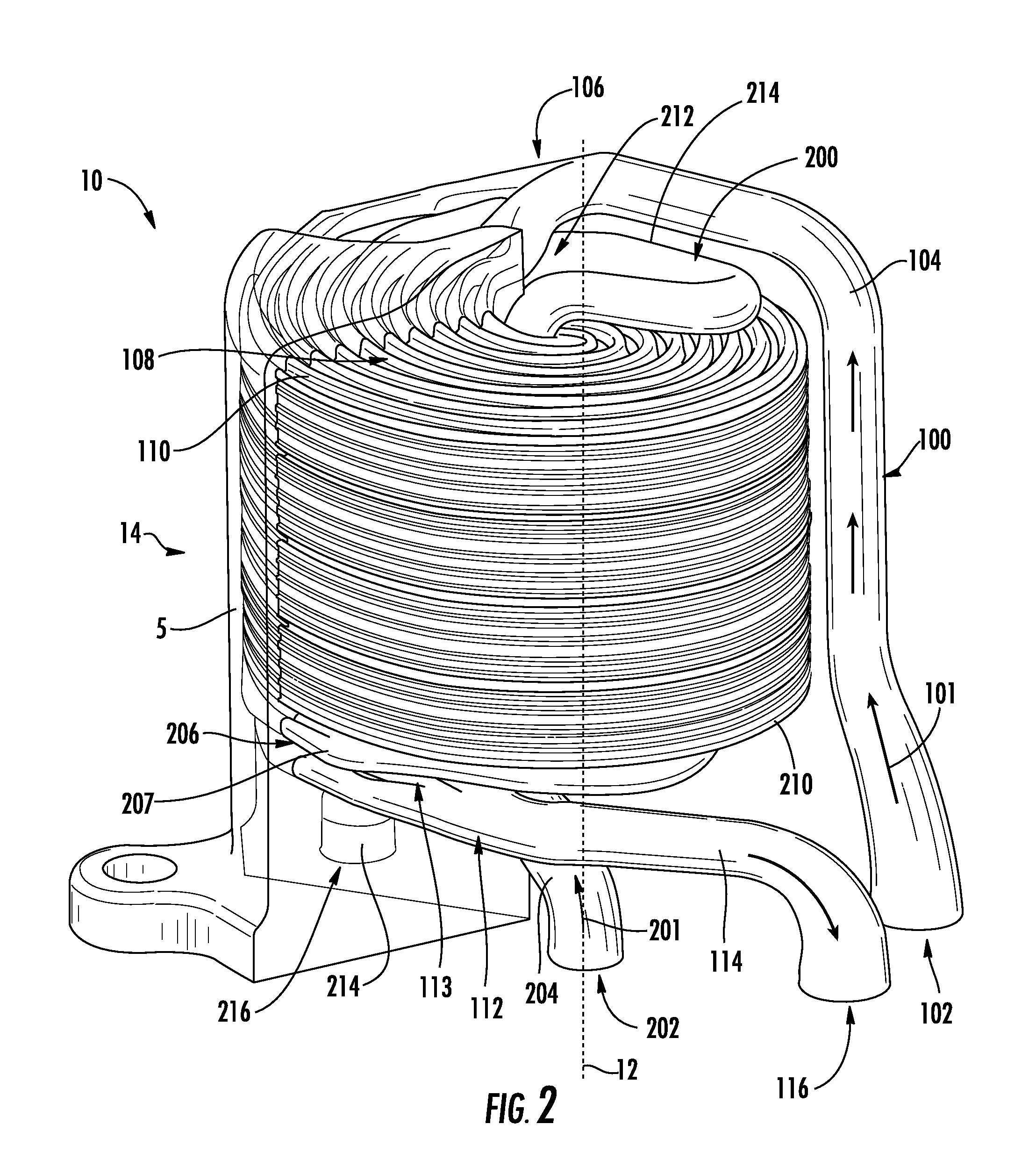
A counter-flow heat exchanger is provided that includes: a first fluid path having a first supply tube connected to a first transition area separating the first fluid path into a first array of first passageways, with the first array of first passageways merging at a first converging area into a first discharge tube; and a second fluid path having a second supply tube connected to a second transition area separating the second fluid path into a second array of second passageways, with the second array of second passageways merge at a second converging area into a second discharge tube. The first passageways and the second passageways have a substantially helical path around the centerline of the counter-flow heat exchanger. Additionally, the first array and the second array are arranged together such that each first passageway is adjacent to at least one second passageway.

Description

FIELD OF THE INVENTION[0001]The present invention relates generally to a counter-flow heat exchanger. In particular embodiments, the counter-flow heat exchanger uses helical passages and transitions from single circular inlet and outlet tubes to multiple passageways with non-circular geometries.BACKGROUND OF THE INVENTION[0002]Heat exchangers may be employed in conjunction with gas turbine engines. For example, a first fluid at a higher temperature may be passed through a first passageway, while a second fluid at a lower temperature may be passed through a second passageway. The first and second passageways may be in contact or close proximity, allowing heat from the first fluid to be passed to the second fluid. Thus, the temperature of the first fluid may be decreased and the temperature of the second fluid may be increased.[0003]Counter-flow heat exchangers provide a higher efficiency than cross-flow type heat exchangers, and are particularly useful when the temperature difference...

Claims


Application Information

Patent Timeline
Patent Type & Authority Applications(United States)
IPC IPC(8): F28D7/02
CPCF28D7/022F28D7/08F28F2210/02F28F7/02F28D7/0008F28F1/06F28F2255/00F28D7/0033
Inventor ROCK, JR., PETER JOSEPHGOLDENBERG, MATTHEWHENNING, LAUREN ASHLEYPRESCOTT, JEFFREY MILES MCMILLENSHANNON, KEVIN ROBERT
Owner GENERAL ELECTRIC CO
Learn More