
Touchscreen panel

a touchscreen panel and touch screen technology, applied in the field of touch screen panels, can solve the problems of difficult to increase the maturity of products, the tsp of the touchscreen panel can be damaged easily by static electricity, and the first connecting pattern b>14/b> can easily be damaged by static electricity, so as to improve the esd problem

Active Publication Date: 2017-02-02
LG DISPLAY CO LTD
View PDF3 Cites 5 Cited by
  • Summary
  • Abstract
  • Description
  • Claims
  • Application Information

AI Technical Summary

Benefits of technology

The patent is about a touchscreen panel that has a conductor rod pattern to improve ESD (electrostatic discharge) problems. The technical effect of this pattern is to reduce static electricity buildup on the touchscreen panel, which can cause damage and other issues.

Problems solved by technology

However, using a separate input device such as a keyboard or mouse requires the user to learn how to use it and also takes up space, making it difficult to increasing the maturity of the products.
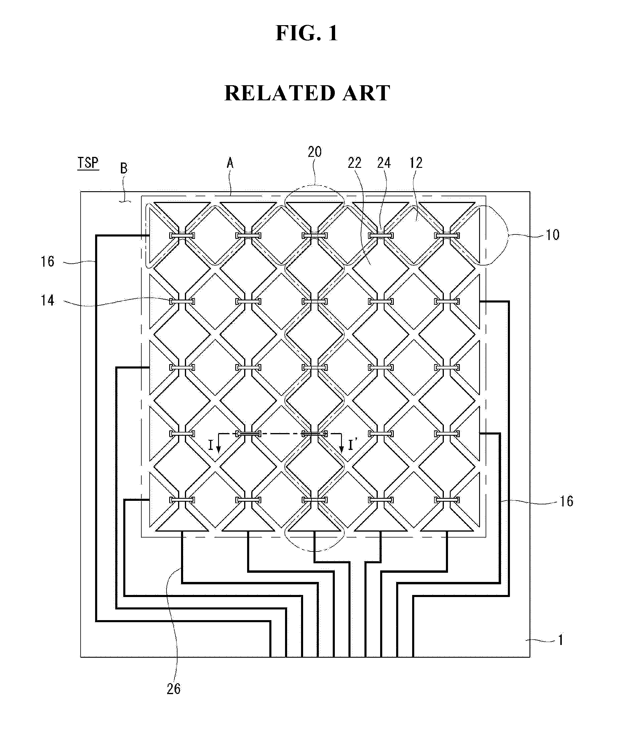
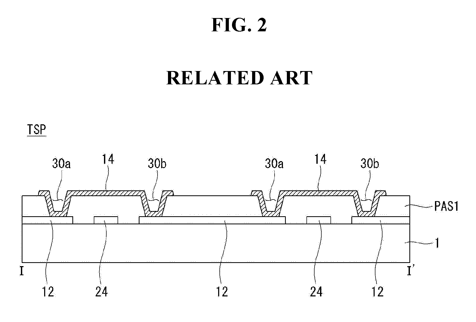
Due to this reason, the first connecting patterns 14 can easily be damaged by static electricity.
The damage to the first connecting patterns 14 may lead to a number of problems, including causing the touchscreen panel TSP to malfunction and decreasing product reliability.

Method used


Image

  • Touchscreen panel
  • Touchscreen panel
  • Touchscreen panel

Examples


first exemplary embodiment

[0030]A touchscreen panel TSP1 according to a first exemplary embodiment of the present invention will be described with reference to FIGS. 3 through 6. FIG. 3 is a plan view of a touchscreen panel according to a first exemplary embodiment of the present invention. FIG. 4 is a cross-sectional view taken along line II-II′ of the touchscreen panel of FIG. 3 according to the first exemplary embodiment of the present invention. FIG. 5 is an enlarged view of the PR area of FIG. 3. FIG. 6 is an enlarged view of the AR area of FIG. 4.

[0031]Referring to FIG. 3, the touchscreen panel TSP1 according to the first exemplary embodiment of the present invention comprises an electrode portion A, a routing wiring portion B, and a pad portion C.

[0032]The electrode portion A comprises a plurality of first electrode lines 110 arranged in parallel to a first direction (e.g., along the X-axis), a plurality of second electrode lines 120 arranged in a second direction (e.g., along the Y-axis) to cross the...

second exemplary embodiment

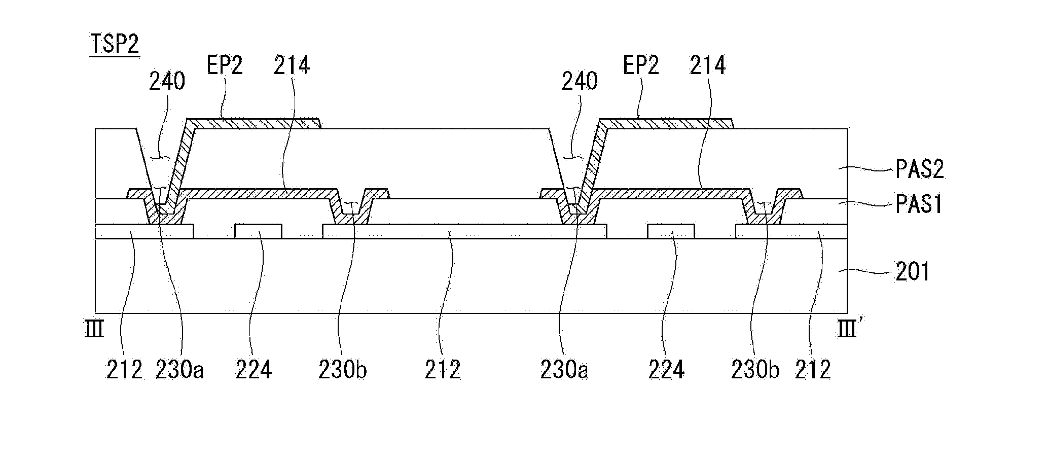
[0051]A touchscreen panel TSP2 according to a second exemplary embodiment of the present invention will be described with reference to FIGS. 7 and 8. FIG. 7 is a plan view of a touchscreen panel according to a second exemplary embodiment of the present invention. FIG. 8 is a cross-sectional view taken along line III-III′ of the touchscreen panel of FIG. 7 according to the second exemplary embodiment of the present invention.

[0052]Referring to FIG. 7, the touchscreen panel TSP2 according to the second exemplary embodiment of the present invention comprises an electrode portion A, a routing wiring portion B, and a pad portion C.

[0053]The electrode portion A comprises a plurality of first electrode lines 210 arranged in parallel to a first direction (e.g., along the X-axis), a plurality of second electrode lines 220 arranged in a second direction (e.g., along the Y-axis) to cross the first electrode lines 210, and conductor rod patterns EP2 electrically connected to the first electrode...


PUM


Abstract

A touchscreen panel includes first and second electrode lines that cross each other with one of the first and second electrode lines being separated from the intersection of the first and second electrode lines, and the separated electrode line being connected to a bridge pattern via lower contact holes penetrating a first insulating film. The touchscreen panel includes a second insulating film covering the first insulating film; and a conductor rod pattern that is electrically connected to the separated electrode line via an upper contact hole penetrating the second insulating film and that overlaps the bridge pattern.

Description

[0001]This application claims the priority benefit of Korean Patent Application No. 10-2015-0109210 filed on Jul. 31, 2015, which is incorporated herein by reference for all purposes as if fully set forth herein.BACKGROUND OF THE INVENTION[0002]Field of the Invention[0003]The present disclosure relates to a touchscreen panel, and more particularly, to a touch screen panel with a conductor rod pattern (or a lightning rod pattern).[0004]Discussion of the Related Art[0005]In recent years, display devices, such as liquid crystal displays, electroluminescent displays, and plasma display panels, having fast response time, low power consumption, and excellent color reproduction, have been in the spotlight. Such display devices have been used for a variety of electronic products such as televisions, monitors for computers, laptop computers, mobile phones, displays on refrigerators, personal digital assistants, and automated teller machines. In general, these display devices interface with a...

Claims


Application Information

Patent Timeline
Patent Type & Authority Applications(United States)
IPC IPC(8): G06F3/041G06F3/044
CPCG06F3/0416G06F2203/04111G06F3/044G06F2203/04112G06F3/0446G06F3/0443
Inventor LEE, NAMSEOKLEE, JUNGHWANHONG, SUNGGONCHA, DONGJOONG
Owner LG DISPLAY CO LTD
Learn More