
System and Method for Minimally Invasive Clavicle Plate Application

a clavicle and application system technology, applied in the field of system and method of minimally invasive clavicle plate application, can solve the problems of insufficient stability, inconvenient clavicle fixation procedure, and incision size,

Active Publication Date: 2017-02-09
DEPUY SYNTHES PROD INC
View PDF0 Cites 48 Cited by
  • Summary
  • Abstract
  • Description
  • Claims
  • Application Information

AI Technical Summary

Benefits of technology

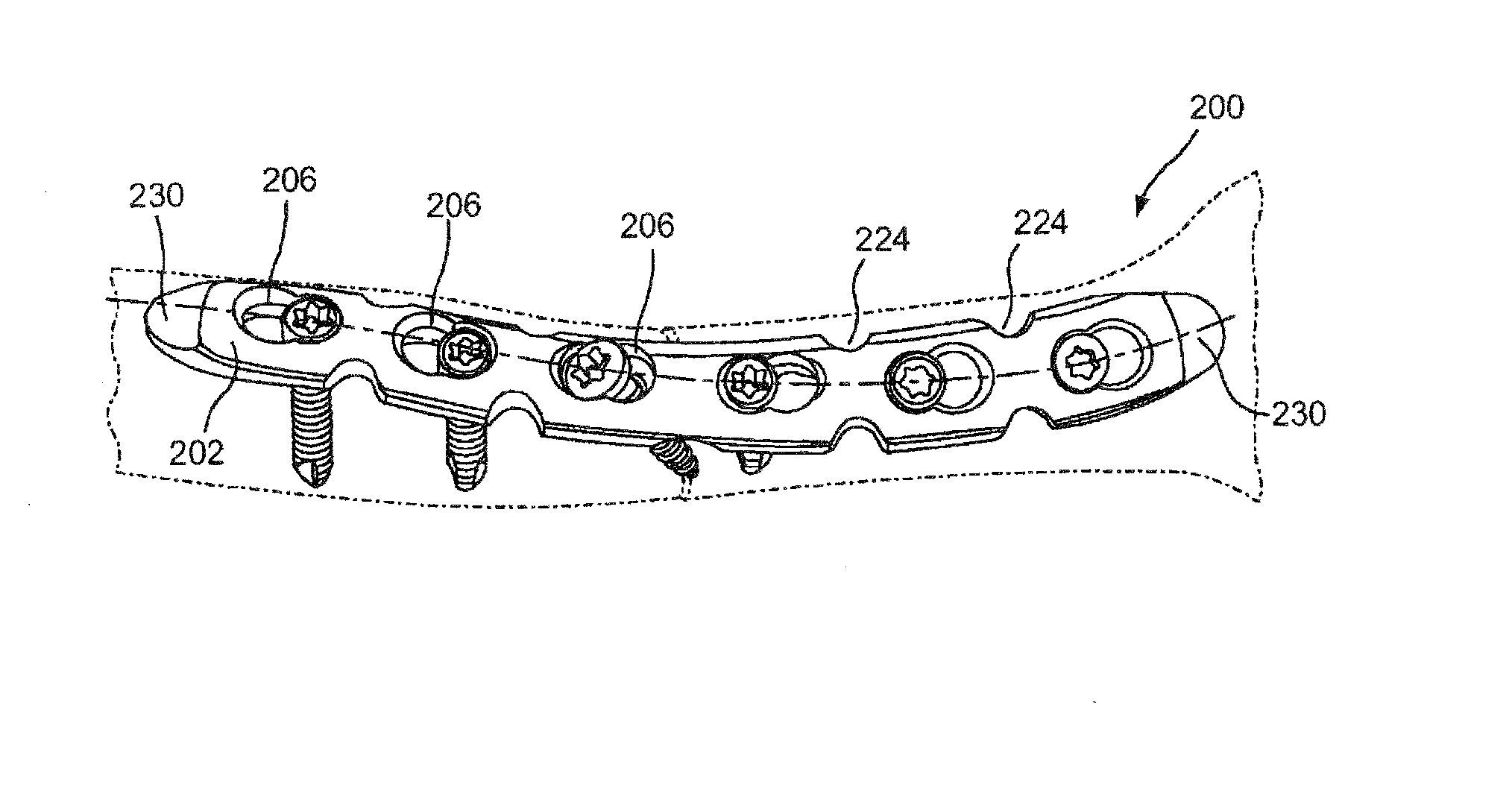
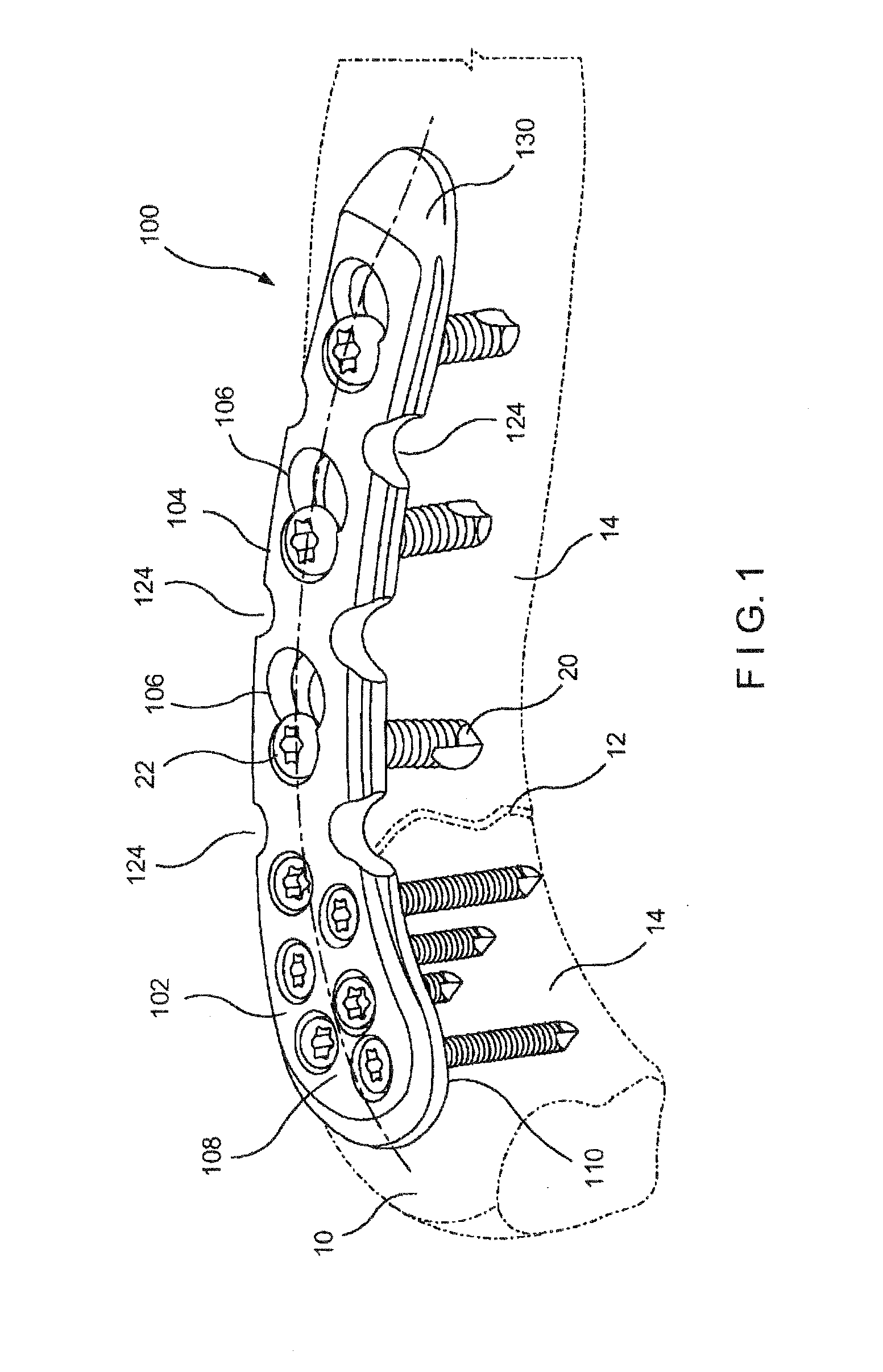
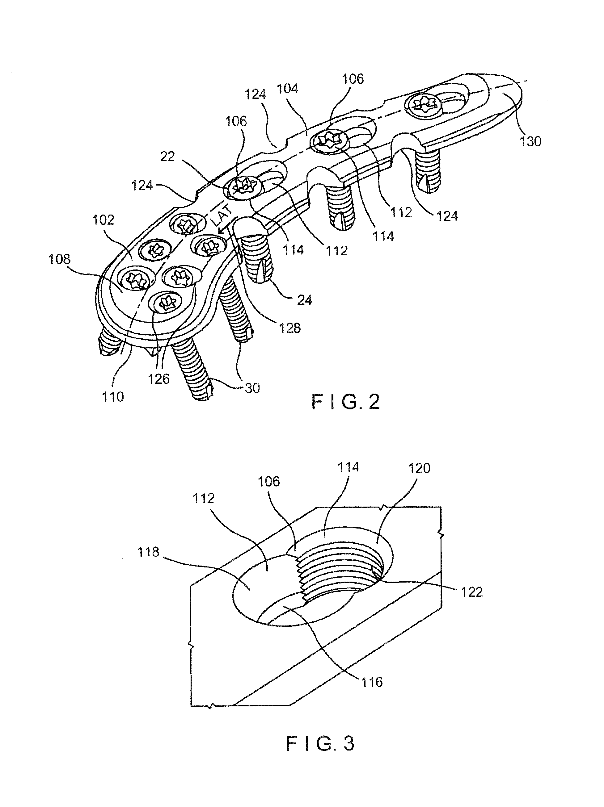
The present invention is a bone fixation plate designed to be used on a clavicle. The plate has an elongated body that conforms to the shape of the clavicle and has a head at one end and a shank at the other end. The shank has a tapered tip that allows for minimally invasive insertion through a small incision near the clavicle. The plate also has two plate holes, one in the shank and one in the head, with the second hole being threaded. This design allows for secure and accurate fixation of the plate to the clavicle in a minimally invasive way.

Problems solved by technology

The size of the incision presents numerous complications including post-operative scarring and irritative complications arising from contact of the procedure site with items of clothing, backpacks, etc.
Furthermore, current clavicle fixation procedures employ Recon plates, which often do not provide adequate stability to a fractured clavicle, sometimes requiring the insertion of a second bone plate to achieve the required stability.

Method used


Image

  • System and Method for Minimally Invasive Clavicle Plate Application
  • System and Method for Minimally Invasive Clavicle Plate Application
  • System and Method for Minimally Invasive Clavicle Plate Application

Examples


Embodiment Construction

[0011]The present invention is directed to a system and method for minimally invasive fixation of clavicle fractures in living bodies. Specifically, the present invention is directed to a system including a bone plate having a plurality of angled bone plate holes and combination plate holes configured to permit an angled inserted of bone screws therethrough. As described in more detail below, a first exemplary bone plate according to the present invention comprises an elongated body with a lateral extension at a first end thereof where a width of the lateral extension (i.e., an extent of the lateral extension in a direction substantially perpendicular to a longitudinal axis of the elongated body) is greater than the width of the elongated body. A second end of this bone plate comprises a tapered tip configured to minimize trauma to adjacent soft tissue as the bone plate is guided through the minimally invasive incision to a target position against the clavicle. In an exemplary embod...


PUM


Abstract

A bone fixation plate, comprises an elongated body contoured to conform to the anatomy of a clavicle, the elongated body comprising a head at a first end and a shaft extending therefrom to a second end, the second end further comprising a reduced diameter tapered tip configured to permit insertion of the elongate body through a minimally invasive incision formed adjacent the clavicle. The bone fixation plate also comprises a first plate hole extending through the shaft from a proximal face to a distal face, the first plate hole formed as a combination hole and a second plate hole extending through the head from the proximal face to the distal face, the second plate hole being threaded.

Description

BACKGROUND[0001]Clavicle fractures are the second most frequently occurring fractures in humans. Osteosynthesis procedures at the clavicle shaft generally require the insertion of a bone plate through an incision approximately 10-15 cm, in length. The size of the incision presents numerous complications including post-operative scarring and irritative complications arising from contact of the procedure site with items of clothing, backpacks, etc. Furthermore, current clavicle fixation procedures employ Recon plates, which often do not provide adequate stability to a fractured clavicle, sometimes requiring the insertion of a second bone plate to achieve the required stability.SUMMARY OF THE INVENTION[0002]The present invention is directed to a bone fixation plate comprising an elongated body contoured to conform to the anatomy of a clavicle, the elongated body comprising a head at a first end and a shaft extending therefrom to a second end, the second end further comprising a reduced...

Claims


Application Information

Patent Timeline
Patent Type & Authority Applications(United States)
IPC IPC(8): A61B17/80
CPCA61B17/8061A61B17/809A61B17/8057
Inventor ANDERMAHR, JONASMAUCH, FLORAREICHLE, CLAUDIABRUN, PHILIPP
Owner DEPUY SYNTHES PROD INC
Learn More