Operating medium tank arrangement for a motor vehicle

a technology for motor vehicles and operating mediums, which is applied in the direction of vehicle components, propulsion parts, transportation and packaging, etc., can solve the problems of large separation volume, and achieve the effects of high separation efficiency, high separation efficiency, and reliable prevention of backlash of operating mediums

Active Publication Date: 2017-02-09
AUDI AG
View PDF3 Cites 11 Cited by
  • Summary
  • Abstract
  • Description
  • Claims
  • Application Information

AI Technical Summary

Benefits of technology

[0023]The second guide tube has for example the same inner diameter as the first guide tube. The second guide tube also serves preferably for guiding or supporting the refueling device. During refueling of the operating medium tank by means of the refueling device the refueling device thus traverses the first guide tube completely and protrudes as far as into the second guide tube. By means of the second guide tube a backsplash of operating medium can be reliably prevented also when the operating medium tank is completely filled and the filling tube is partially filled with operating medium.
[0024]Accordion to another advantageous feature of the invention, the separating web, the further separating web and the deflection web extend parallel to each other. Such a configuration was mentioned above. Correspondingly a flow deflection of 180° is realized by the separating web, the further separating web and the deflection web. The mixture is conducted by the deflection web into an intermediate space located between the separating web and the further separating web, which intermediate space on its side that faces away from the guide insert, extends preferably as far as to the bottom wall surface of the separator housing. As a result of the flow deflection by 180° that occurs in this intermediate space the liquid operating medium can be separated from the mixture very efficiently.
[0025]Accordion to another advantageous feature of the invention, the separating web, the further separating web and the deflection web are angled relative to a plane that is perpendicular to the longitudinal center axis of the second filling tube. This means that the mentioned webs are not parallel to the imagined plane but rather form angles with the imagined plane. The angle is hereby greater than 0° and smaller than 180°. Preferably the angle is smaller than 90°. For example the angle is at least 10°, at least 20°, at least 30°, at least 40° or at least 45°. In this way the very space saving configuration of the liquid separator is realized while at the same time ensuring a high separation efficiency.

Problems solved by technology

This results in a very large separating volume.

Method used


Image

  • Operating medium tank arrangement for a motor vehicle
  • Operating medium tank arrangement for a motor vehicle
  • Operating medium tank arrangement for a motor vehicle

Examples


Embodiment Construction

[0030]Throughout all the Figures, same or corresponding elements may generally be indicated by same reference numerals. These depicted embodiments are to be understood as illustrative of the invention and not as limiting in any way. It should also be understood that the figures are not necessarily to scale and that the embodiments are sometimes illustrated by graphic symbols, phantom lines, diagrammatic representations and fragmentary views. In certain instances, details which are not necessary for an understanding of the present invention or which render other details difficult to perceive may have been omitted.

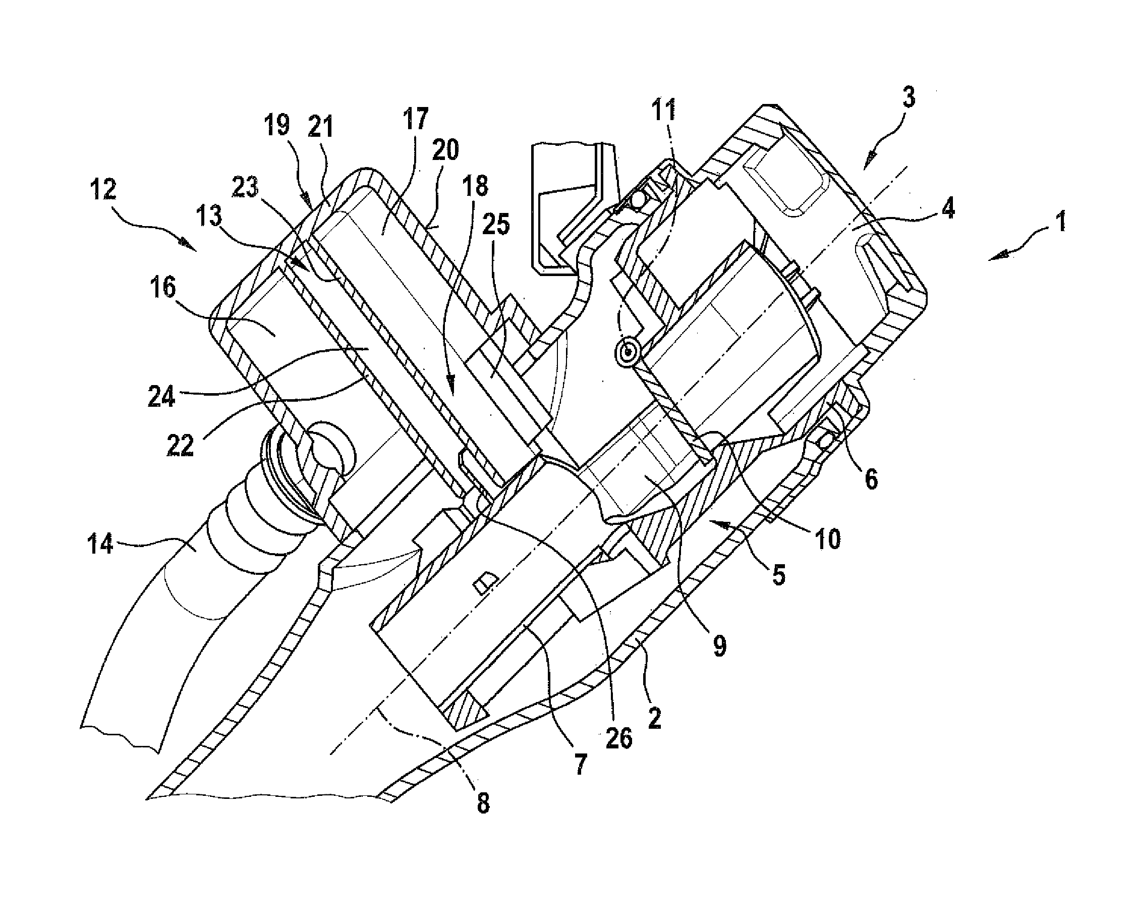
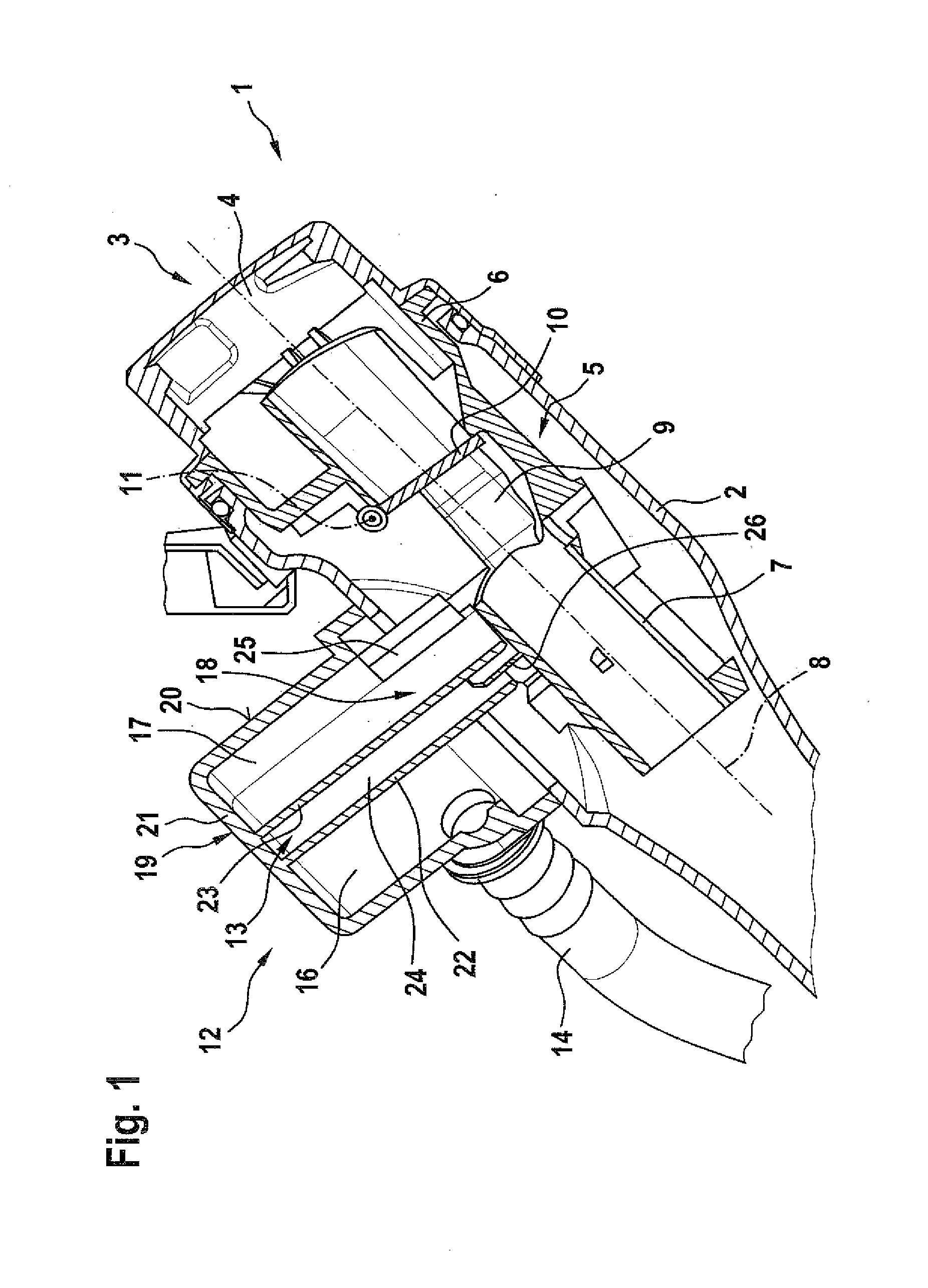
[0031]FIG. 1 shows a longitudinal section through a region of an operating medium tank arrangement 1, which has a here not further shown operating medium tank and a filling tube 2. The filling tube 2 serves for refueling the operating medium tank with operating medium. For this purpose the filling tube 2 is fluidly connected on one side with the operating medium tank. On the...


PUM


Abstract

An operating medium tank arrangement for a motor vehicle includes an operating medium tank; a filling tube for refueling the operating medium tank, wherein the filling tube is fluidly connected on one side to the operating medium tank and on the other side has an insertion opening for receiving a refueling device; a guide insert arranged in the filling tube for guiding the refueling device; and a liquid separator including a separator chamber which is divided into a first sub-chamber and a second sub-chamber, wherein the first sub-chamber is fluidly connected to the operating medium tank via a ventilation line, wherein the second sub-chamber is fluidly connected to a filter device, wherein the separator chamber is fluidly connected to the filling tube for purging operating medium separated in the liquid separator into the filling tube, and wherein the first sub-chamber and the second sub-chamber are fluidly connected with each other via a labyrinth separator which is formed by the liquid separator and the filling tube.

Description

CROSS-REFERENCES TO RELATED APPLICATIONS[0001]This application claims the priority of German Patent Application, Serial No. 10 2015 010 354.7, filed Aug. 6, 2015, pursuant to 35 U.S.C. 119(a)-(d), the content of which is incorporated herein by reference in its entirety as if fully set forth herein.BACKGROUND OF THE INVENTION[0002]The present invention relates to an operating medium tank arrangement for a motor vehicle.[0003]The following discussion of related art is provided to assist the reader in understanding the advantages of the invention, and is not to be construed as an admission that this related art is prior art to this invention.[0004]An operating medium arrangement is assigned to the motor vehicle or forms a part of the motor vehicle. It serves for storing or temporarily storing fuel, which can in particular be used for operating a drive aggregate of the motor vehicle. Operating medium includes for example fuel, in particular benzene or diesel. In this case the operating ...

Claims


Application Information

Patent Timeline
Patent Type & Authority Applications(United States)
IPC IPC(8): B60K15/04
CPCB60K2015/0458B60K15/04B60K15/035B60K2015/03509B60K2015/03552B60K2015/0461
Inventor HAGEN, HARALD
Owner AUDI AG
Why Eureka
Try Eureka