Wheel disk assembly and method for assembling a wheel disk assembly

a technology of wheel disk and assembly method, which is applied in the direction of leakage prevention, machine/engine, engine fuction, etc., can solve the problems of mounting sealing and incurring considerable expens

Inactive Publication Date: 2017-02-09
SIEMENS AG
View PDF5 Cites 8 Cited by
  • Summary
  • Abstract
  • Description
  • Claims
  • Application Information

AI Technical Summary

Benefits of technology

[0006]Starting from this prior art, an object of the present invention is to provide a wheel disk arrangement of the type mentioned at the beginning, in which the sealing plates can be dismounted and remounted easily.

Problems solved by technology

A disadvantage of the known wheel disk arrangements consists in it being possible to dismount the sealing plates for servicing only with difficulty because two adjacent blade devices need to have been removed first, which in practice incurs considerable expense.

Method used


Image

  • Wheel disk assembly and method for assembling a wheel disk assembly
  • Wheel disk assembly and method for assembling a wheel disk assembly
  • Wheel disk assembly and method for assembling a wheel disk assembly

Examples


first embodiment

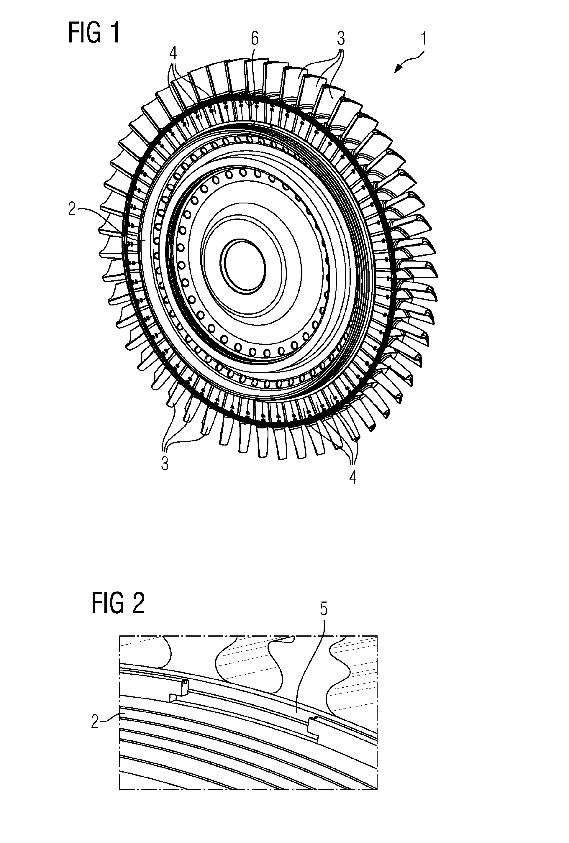
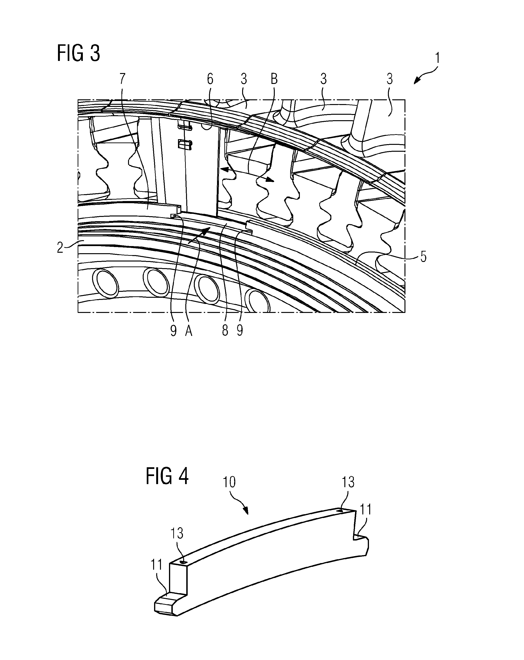
[0037]FIGS. 1 to 6 show a wheel disk arrangement 1 according to the present invention. The wheel disk arrangement 1 comprises a wheel disk 2, multiple blade devices 3 which are fastened along the outer circumference of the wheel disk 2, and multiple sealing plates 4 which are held between the wheel disk 2 and the blade devices 3 in two annular grooves 5 and 6 spaced apart from each other radially. The first annular groove 5 is here provided in the wheel disk 2 and is delimited axially outward by an annular projection 7. The second annular groove 6 is defined by multiple annular groove segments which are arranged adjacent to one another and formed in each case in the blade devices 3.

[0038]In order to facilitate the mounting of the sealing plates 4, the wheel disk 2 comprises at least one recess 8 which extends axially through the annular projection 7 and the minimum width of which in the circumferential direction is greater than the width of the sealing plates 4 at the internal diame...

second embodiment

[0043]FIGS. 7 to 13 show a wheel disk arrangement 14 according to the present invention. The wheel disk arrangement 14 comprises a wheel disk 15, multiple blade devices 16 which are fastened along the outer circumference of the wheel disk 15, and multiple sealing plates 17 which are held between the wheel disk 15 and the blade devices 16 in two annular grooves 18 and 19 spaced apart radially from each other. The first annular groove 18 is here provided in the wheel disk 15 and is delimited axially outward by an annular projection 20. The second annular groove 19 is defined by multiple adjacently arranged annular groove segments which are each designed in the blade devices 16.

[0044]In order to facilitate the mounting of the sealing plates 17, the wheel disk 15 comprises at least one recess 21 extending axially through the annular projection 20 and the minimum width of which in the circumferential direction is greater than the width of the sealing plates 17 at the internal diameter. C...

third embodiment

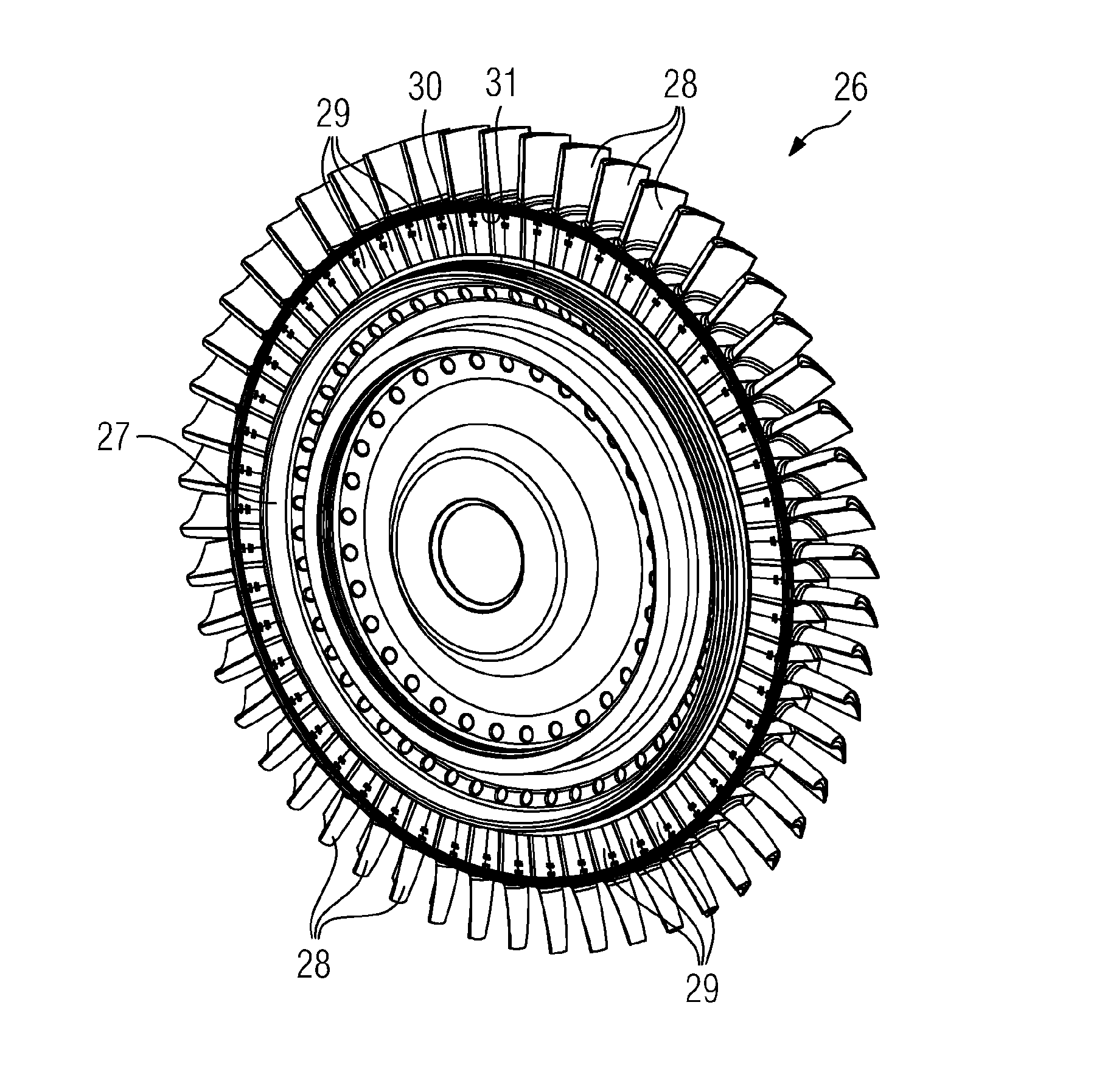
[0049]FIGS. 14 to 18 show a wheel disk arrangement 26 according to the present invention. The wheel disk arrangement 26 comprises a wheel disk 27, multiple blade devices 28 which are fastened along the outer circumference of the wheel disk 27, and multiple sealing plates 29 which are held between the wheel disk 27 and the blade devices 28 in two annular grooves 30 and 31 spaced apart radially from each other. The first annular groove 30 is here provided in the wheel disk 27 and is delimited axially outward by an annular projection 32. The second annular groove 31 is defined by multiple adjacently arranged annular groove segments which are each designed in the blade devices 28.

[0050]In order to facilitate the mounting of the sealing plates 29, the wheel disk 27 comprises at least one recess 33 extending axially through the annular projection 32 and the minimum width of which in the circumferential direction is greater than the width of the sealing plates 29 at the internal diameter. ...


PUM


Abstract

A wheel disk assembly, having a wheel disk, a plurality of blade devices, which are fastened along the outer circumference of the wheel disk, and a plurality of sealing plates, which are retained in two annular grooves radially spaced apart from each other, the first annular groove in the wheel disk and bounded axially outward by an annular projection, and the second annular groove defined by a plurality of annular-groove segments arranged adjacently, which are in the individual blade devices. At least one opening extends axially through the annular projection, the minimum width of which opening in the circumferential direction is greater than the width of the sealing plates at the inside diameter such that a sealing plate is axially insertable between the annular grooves through the opening and moveable in the circumferential direction while guided by the annular grooves. A method assembles such a wheel disk assembly.

Description

CROSS REFERENCE TO RELATED APPLICATIONS[0001]This application is the US National Stage of International Application No. PCT / EP2015 / 057053 filed Mar. 31, 2015, and claims the benefit thereof. The International Application claims the benefit of European Application No. EP14166363 filed Apr. 29, 2014. All of the applications are incorporated by reference herein in their entirety.FIELD OF INVENTION[0002]The present invention relates to a wheel disk arrangement having a wheel disk, multiple blade devices which are fastened along the outer circumference of the wheel disk, and multiple sealing plates which are held in two annular grooves spaced radially apart from each other, wherein the first annular groove is provided in the wheel disk and delimited axially outward by an annular projection, and wherein the second annular groove is defined by multiple annular groove segments which are arranged adjacent to one another and provided in each case in the individual blade devices.BACKGROUND OF ...

Claims


Application Information

Patent Timeline
Patent Type & Authority Applications(United States)
IPC IPC(8): F01D5/30F01D11/00
CPCF01D5/3015F05D2230/60F01D11/006F01D5/326F05D2260/30F05D2260/31F05D2260/36
Inventor DUNGS, SASCHAHOELL, HARALDKAMPKA, KEVINKOLK, KARSTENLANGE, MARCSCHRODER, PETERVEITSMAN, VYACHESLAV
Owner SIEMENS AG
Why Eureka
Try Eureka