Wire tightening apparatus

a technology of tightening apparatus and wire, which is applied in the direction of fastenings, footwear, shoe lace fastenings, etc., can solve the problems of inconvenient and stably tightening procedures of shoestrings, product durability and reliability may be degraded, product error, etc., to improve product quality and reliability, facilitate and stably tighten or loosen shoestrings, the effect of simplifying the procedur

Active Publication Date: 2017-02-16
SHINKYUNG INC
View PDF0 Cites 2 Cited by
  • Summary
  • Abstract
  • Description
  • Claims
  • Application Information

AI Technical Summary

Benefits of technology

[0017]The wire tightening apparatus according to the present invention has the following effects through the aforementioned resolutions.
[0018]First, the wire tightening apparatus allows to conveniently and stably tighten or loosen shoestrings through a simplified procedure, thus greatly enhancing the quality and reliability of the products. The wire tightening apparatus is configured in such a way that a resilient restriction part is provided integral at an intermediate member, wherein the resilient restriction part is employed as a means to maintain an lifting state for selectively eliminating the engaged state between the intermediate member and the winding member, for which...

Problems solved by technology

However, for the elementary school students of lower grades or kids before the elementary school or senior citizens, the loosening and tightening procedures of the shoestrings are not easy.
For athletes and ordinary persons who do exercises, for example, a mounting climbing and a cycle racing, if both ends or a knotted portion of the shoestring are not fixed and untied when it is caught through an intense action or by an external thing, a racing record may be lowered, and an accident may occur, thus causing an undesired result.
Moreover, the aforementioned shoestring tightening d...

Method used


Image

  • Wire tightening apparatus
  • Wire tightening apparatus
  • Wire tightening apparatus

Examples


Embodiment Construction

[0029]The wire tightening apparatus according to a preferred embodiment of the present invention will be described with reference to the accompanying drawings.

[0030]FIG. 3 is a disassembled side view illustrating a wire tightening apparatus according to an exemplary embodiment of the present invention. FIG. 4 is a sectional plan view illustrating a relationship between an intermediate member and a ratchet type of gear according to an exemplary embodiment of the present invention.

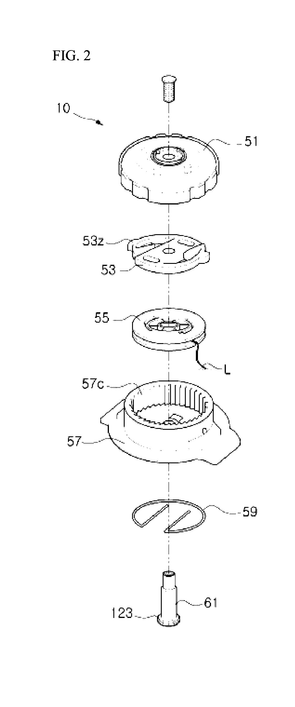
[0031]As illustrated in FIGS. 3 and 4, the wire tightening apparatus 100 may include, but is not limited to, a housing 157, a winding member 155, a support part 160 and an intermediate member 153.

[0032]A circumferential one-direction ratchet type of gear (157c in FIG. 4) is formed at the upper of an inner periphery of the housing 157. It is preferred that through holes 157d through which the wire (L) used as a shoestring passes through to the outside, are formed at a previously set side portion.

[0033]Moreove...


PUM


Abstract

In order to significantly improve productivity and durability by simplifying a configuration, the present invention provides a wire tightening apparatus comprising: a housing having a ratchet type of gear formed in the inner periphery thereof in a circumferential direction; a winding member inserted into the housing so as to be rotatable, a wire being selectively wound therearound; a support part radially protruding from the upper portion of a coupling shaft of which the lower portion is coupled to the housing; and an intermediate member that includes an engagement restriction part selectively engaged with the ratchet type of gear and restricted from rotating in a direction, and has a resilient coupling hole formed in the center thereof, the periphery of which a resilience restriction part is formed on, wherein the engagement restriction part is provided on an end portion of a blade part extending from a body part and having a resilient support force, and the resilience restriction part is elevated by an external force to be selectively coupled to the upper portion of the winding member and is supported by the outer periphery of the support part in a lifted state and in a lowered state.

Description

TECHNICAL FIELD[0001]The present invention relates to a wire tightening apparatus, and in particular to a wire tightening apparatus wherein the wire tightening apparatus can be configured into a simplified form, and an assembling procedure can be convenient, for which the productivity and durability may be greatly enhanced.BACKGROUND[0002]The shoes, for example, sneakers, etc. are equipped with a shoestring tied in a zigzag shape, thus allowing the shoes to tightly fit to a user's foot size. The tight fitting between the shoes and the user's feet can be improved by pulling and tightening the shoestrings, whereby a convenient walking can be achieved.[0003]However, for the elementary school students of lower grades or kids before the elementary school or senior citizens, the loosening and tightening procedures of the shoestrings are not easy. For athletes and ordinary persons who do exercises, for example, a mounting climbing and a cycle racing, if both ends or a knotted portion of th...

Claims


Application Information

Patent Timeline
IPC IPC(8): A43C7/08B65H75/30A44B99/00A43C11/16
CPCA43C7/08A44B99/00B65H75/30A43C11/16A43C11/165B65H75/4431Y10T24/216Y10T24/2183Y10T24/3724A43C11/20
Inventor HA, GI HOHA, YOUNG HOKIM, HYUN IL
Owner SHINKYUNG INC
Why Eureka
Try Eureka