Juicer

Inactive Publication Date: 2017-02-16
LIN WEI CHIH +3
View PDF1 Cites 2 Cited by
  • Summary
  • Abstract
  • Description
  • Claims
  • Application Information

AI Technical Summary

Benefits of technology

[0005]A primary objective of the present invention is to provide a juicer which employs an axis of a motor with two ends connected with a unidirectional bearing respectively, and a controller for controlling the rotational directions of the axis for selectively enabling one of two different cutt

Problems solved by technology

However, when users only need to use one of the containers for cutting, the above-mentioned structures do not leave the users many choices.
Because the two cutters inside the two containers turn simultaneously, not

Method used


Image

  • Juicer
  • Juicer
  • Juicer

Examples


Example

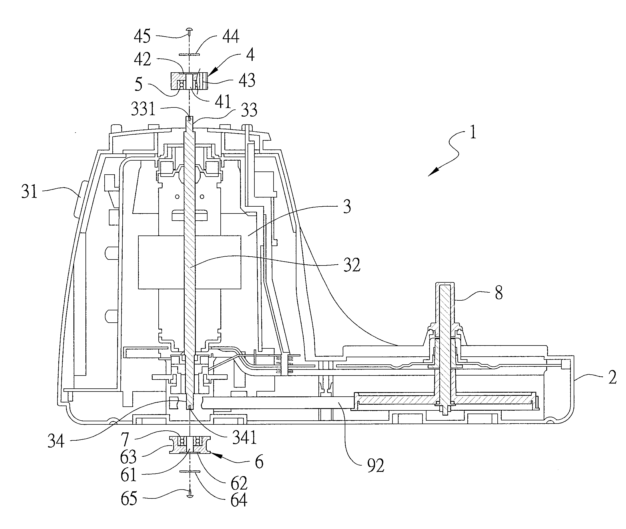
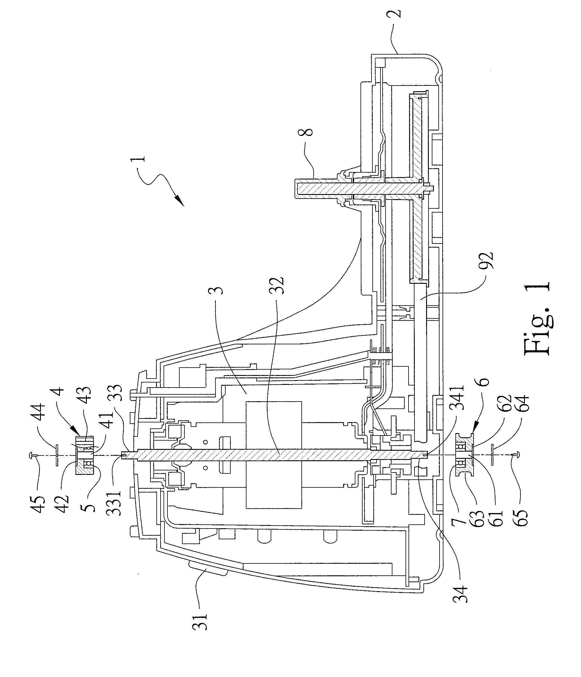
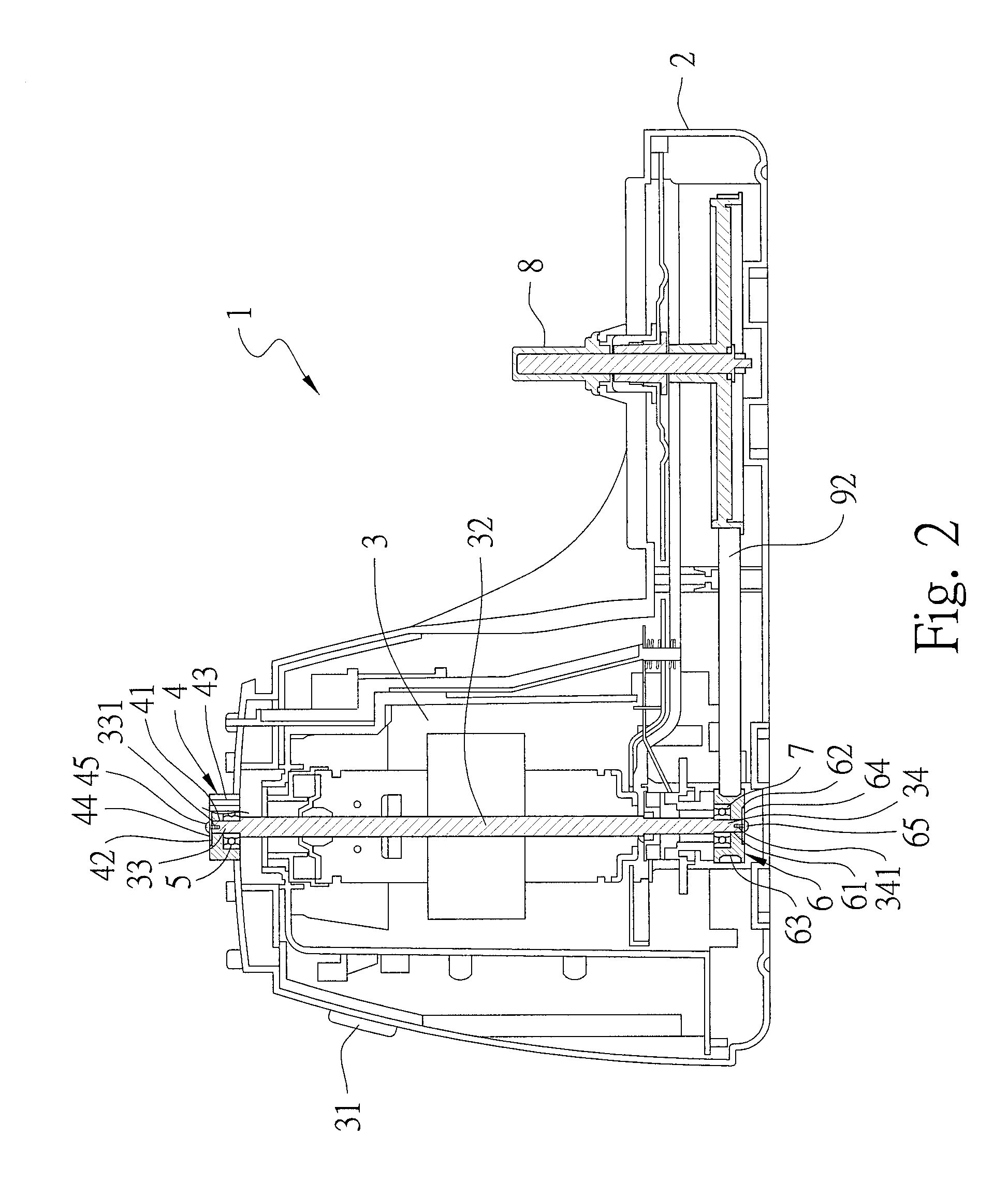
[0016]Please refer to FIGS. 1 and 2 for a juicer 1 according to a preferred embodiment of the present invention. The juicer 1 comprises a base 2, a motor 3, a first connecting element 4, a first unidirectional bearing 5, a second connecting element 6, a second unidirectional bearing 7 and a third connecting element 8.

[0017]The motor 3 is a servomotor vertically positioned inside the base 2. The motor 3 is electrically connected with a controller 31 for controlling an axis 32 of the motor 3 to turn clockwise or anti-clockwise. The axis 32 of the motor 3 has a first end 33 and a second end 34 in an opposite direction to the first end 33. The first end 33 is disposed at a top of the axis 32, and the second end 34 is disposed at a bottom of the axis 32. Screw holes 331 and 341 are disposed at an end face of the first end 33 and the second end 34 respectively.

[0018]The first connecting element 4 is a short cylindrical column having a hollow axial hole 41. A groove 42 is concavely formed ...


PUM


Abstract

A juicer comprises a base. A motor electrically connected to a controller disposed inside the base. The controller controls an axis of the motor to turn clockwise or anti-clockwise. The axis of the motor has a first end and a second end in an opposite direction to the first end. The first end of the axis is axially connected with a first unidirectional bearing coupled with a first connecting element coaxially. The second end of the axis is axially connected with a second unidirectional bearing coupled with a second connecting element coaxially. The second connecting element is moved together with a third connecting element. Thereby, the axis of the motor turns in clockwise or anti-clockwise direction for selectively enabling the first connecting element to move upwardly together with a first cutter inside a first container and to turn the first cutter for cutting.

Description

FIELD OF THE INVENTION[0001]The present invention relates to a juicer and more particularly to a juicer that selectively enables one of two different cutters to turn and perform cutting so that electrical energy can be effectively saved, lifespan of the juicer can be prolonged, and noise produced during usage can be reduced.BACKGROUND OF THE INVENTION[0002]Different types of juicers are available in the market for grinding, cutting and making juice from fruits, vegetables and foods for people to intake nutrients. Please refer to FIG. 5. FIG. 5 shows a conventional juicer with two containers b and b1. Two different cutters c and c1 disposed inside the two containers b and b1 respectively are moved together with a motor d so that the cutters c and c1 can turn at a high speed and a low speed respectively for performing different cutting effects.[0003]However, when users only need to use one of the containers for cutting, the above-mentioned structures do not leave the users many choice...

Claims


Application Information

Patent Timeline
IPC IPC(8): A47J43/07A47J43/08
CPCA47J43/085A47J43/0716A47J43/087A47J44/00A47J19/02
Inventor LIN, TZU-NUNG
Owner LIN WEI CHIH
Why Eureka
Try Eureka