Intramedullary anchor-screw fracture fixation

a technology of applied in the field of intramedullary anchoring and fixing fractures, can solve problems such as large scars, and achieve the effects of minimal scarring, minimal scarring, and minimal treatmen

Inactive Publication Date: 2017-02-16
EXTREMITY DESIGNS
View PDF4 Cites 0 Cited by
  • Summary
  • Abstract
  • Description
  • Claims
  • Application Information

AI Technical Summary

Benefits of technology

[0004]This new invention in fracture fixation allows for minimally invasive treatment with minimal scarring. It is therefore an object of this invention to provide minimally invasive fracture fixation in the diaphysis of long bones, including: the ulna, clavicle, humerus, radius, carpals, metacarpals, phalanges, femur, tibia, fibula, tarsals and metatarsals.
[0006]To position the current invention into the fractured bone, the surgeon would follow the following procedure: An incision would be made at one side of the fracture. A drill bit would then be used to drill through both fragments. The bi-threaded nut would be screwed through the first fragment and then on to the second fragment. The screw would then be used to anchor the first fragment onto the second fragment by locking into the bi-threaded nut. The two fragments would be compressed against each other to prevent torsional instability. The wound is then sutured closed, creating minimal scarring.

Problems solved by technology

Once the plate is in place, the wound is sutured closed, leaving behind a large scar.

Method used


Image

  • Intramedullary anchor-screw fracture fixation
  • Intramedullary anchor-screw fracture fixation
  • Intramedullary anchor-screw fracture fixation

Examples


Embodiment Construction

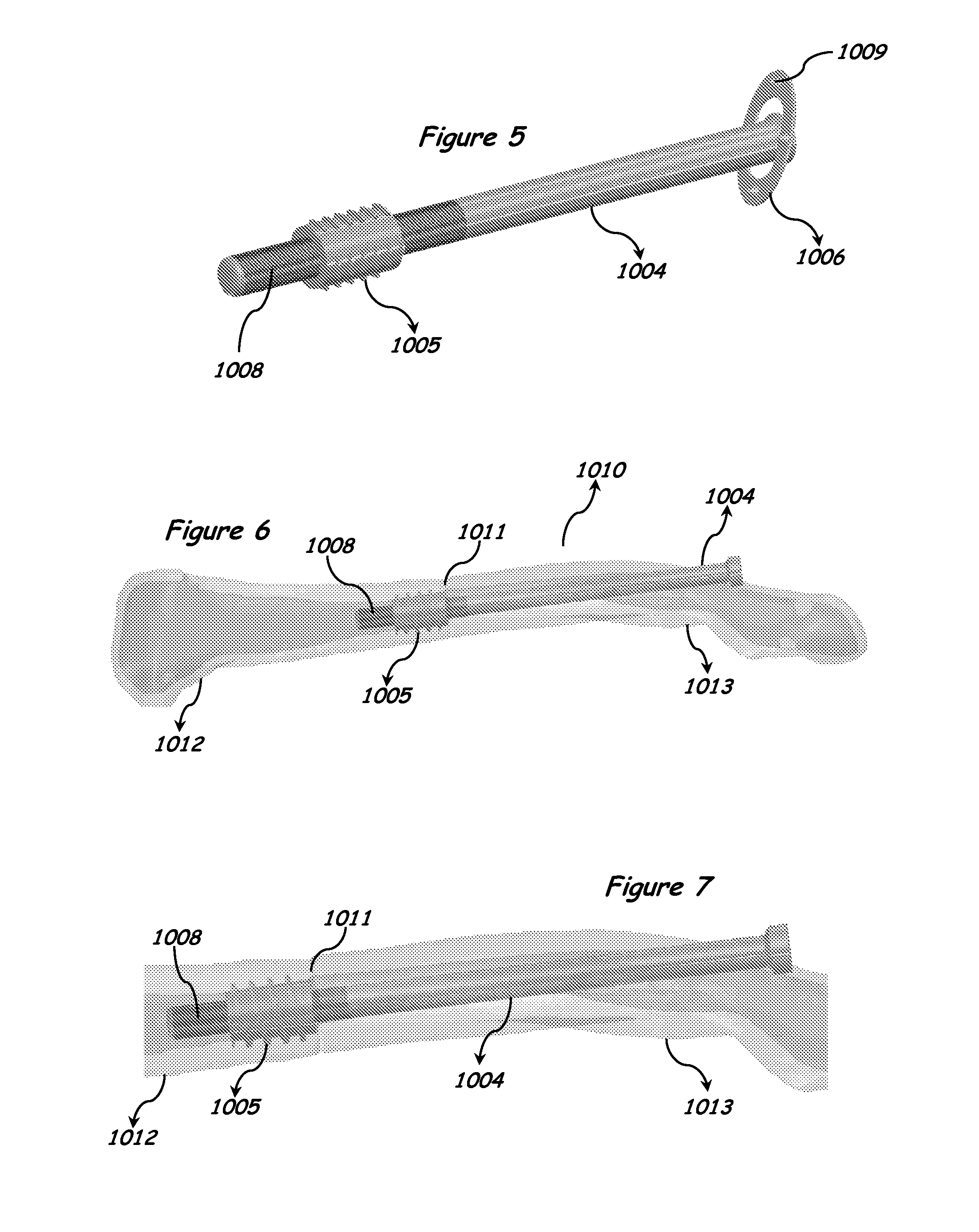
[0015]The preferred embodiment of the present invention is shown in FIGS. 1-7.

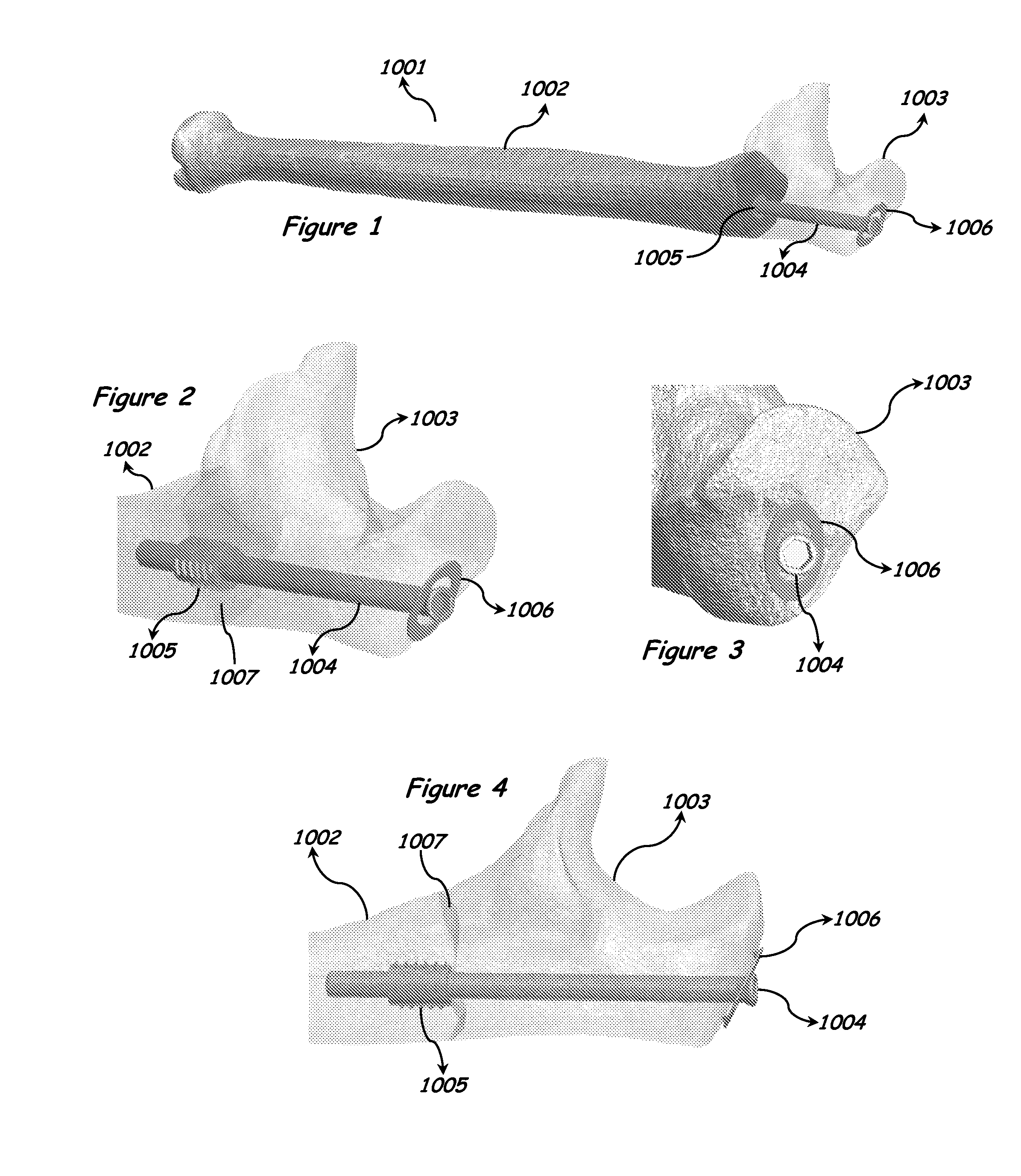
[0016]As shown in FIG. 1, a perspective view of the ulna 1001 showing a distal fracture fragment 1002 and a proximal fracture fragment 1003. The anchor-screw device consists of: a distal threaded nut 1005 that is screwed into the distal fragment 1002, a proximal screw 1004 that is implanted through a hole in the proximal fragment 1003, and a spiked washer 1006 that is inserted between the proximal fragment 1003 and the proximal screw 1004.

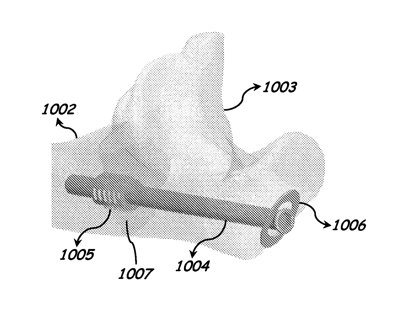
[0017]As shown in FIG. 2, a perspective view of the elbow showing the proximal fragment 1003, the distal fragment 1002 and the fracture site 1007, the threaded nut 1005, the proximal screw 1004 and the spiked washer 1006.

[0018]As shown in FIG. 3, a close-up view of the elbow showing the proximal fragment 1003, the proximal screw 1004 and the spiked washer 1006.

[0019]As shown in FIG. 4, a side view of the elbow showing the proximal fragment 1003, the distal fragment 1002 a...


PUM


Abstract

The present invention relates to an improved intramedullary fracture fixation device, the device including a first fastener comprising a head and an at least partially threaded shaft extending from the head, a tiltable load spreading element adapted to couple to the first fastener and having a bone-contacting surface defining bone engagement features and a head-contacting surface, and a second fastener having external threads and a central bore for receiving the threaded shaft of the first fastener. The central bore defines an inner wall surface which is at least partially threaded, the inner wall surface being configured for mating engagement on the outer surface of the shaft of the first fastener such that rotation of the first fastener relative to the second fastener causes the translation of the first fastener relative to the second fastener along the shaft. The load spreading element is configured and dimensioned to interact operatively with at least a surface of the bone and at least a surface of the head to spread the load exerted by the head on the bone over a large bone surface area and, optionally, to prevent the head from completely passing through the bone. The present invention permits a minimally invasive repair of bone fractures that may otherwise be treated through larger incisions. The present invention also relates to the method of fixation of the device.

Description

FIELD OF INVENTION[0001]This invention relates to intramedullary fracture fixation. More specifically, this invention relates to a multi-piece anchor-screw construct intended for intramedullary fixation of long bone fractures.BACKGROUND OF THE INVENTION[0002]Severe bone fractures are most commonly repaired with open reduction and internal fixation using plates and screws attached to the cortex of the bone. The preferred method to gain access to the fracture site is by making a large incision through the skin and muscles. Once the fracture has been exposed, the plate is then attached to the bone fragment(s) using screws. The placement of the bone plate will aid in healing by minimizing the amount of interfragmentary movement. Once the plate is in place, the wound is sutured closed, leaving behind a large scar.[0003]Intramedullary anchor-screw fixation gives the surgeon an alternative to plate fixation by creating a minimally invasive procedure with better aesthetic, as well as functi...

Claims


Application Information

Patent Timeline
Patent Type & Authority Applications(United States)
IPC IPC(8): A61B17/72
CPCA61B17/7233A61B17/7258A61B17/7266A61B17/8685A61B17/8695
Inventor MIGHELL, MARK ALLENGUTIERREZ, SERGIO
Owner EXTREMITY DESIGNS
Why Eureka
Try Eureka