Treatment tool
a technology of treatment tool and target tissue, which is applied in the field of treatment tool, can solve the problems of obstructing the minimally invasive treatment of the target tissue and the difficulty of shortening the time required to treat the living tissue, and achieve the effect of reducing treatment time and performing minimally invasive treatmen
- Summary
- Abstract
- Description
- Claims
- Application Information
AI Technical Summary
Benefits of technology
Problems solved by technology
Method used
Image
Examples
embodiment 1
Makeup Outline of a Treatment System
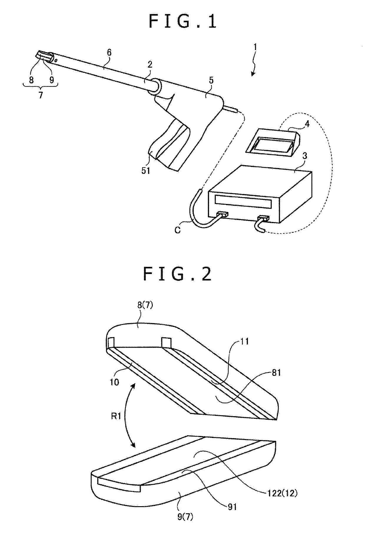
[0022]FIG. 1 is a view illustrating a treatment system 1 according to Embodiment 1 of the present disclosure.
[0023]The treatment system 1 treats, e.g., joins or anastomoses, separates, or otherwise processes, a living tissue by applying energy, e.g., thermal energy or electric energy (high-frequency energy), to the living tissue. As illustrated in FIG. 1, the treatment system 1 includes a treatment tool 2, a controller 3, and a foot switch 4.
[0024]Makeup of the Treatment Tool
[0025]The treatment tool 2 is a linear-type surgical treatment tool for treating a living tissue through an abdominal wall, for example. As illustrated in FIG. 1, the treatment tool 2 includes a handle 5, a sheath or shaft 6, and a grasper 7.
[0026]The handle 5 is a part by which the surgeon holds the treatment tool 2 by hand. As illustrated in FIG. 1, the handle 5 has a manipulating knob 51.
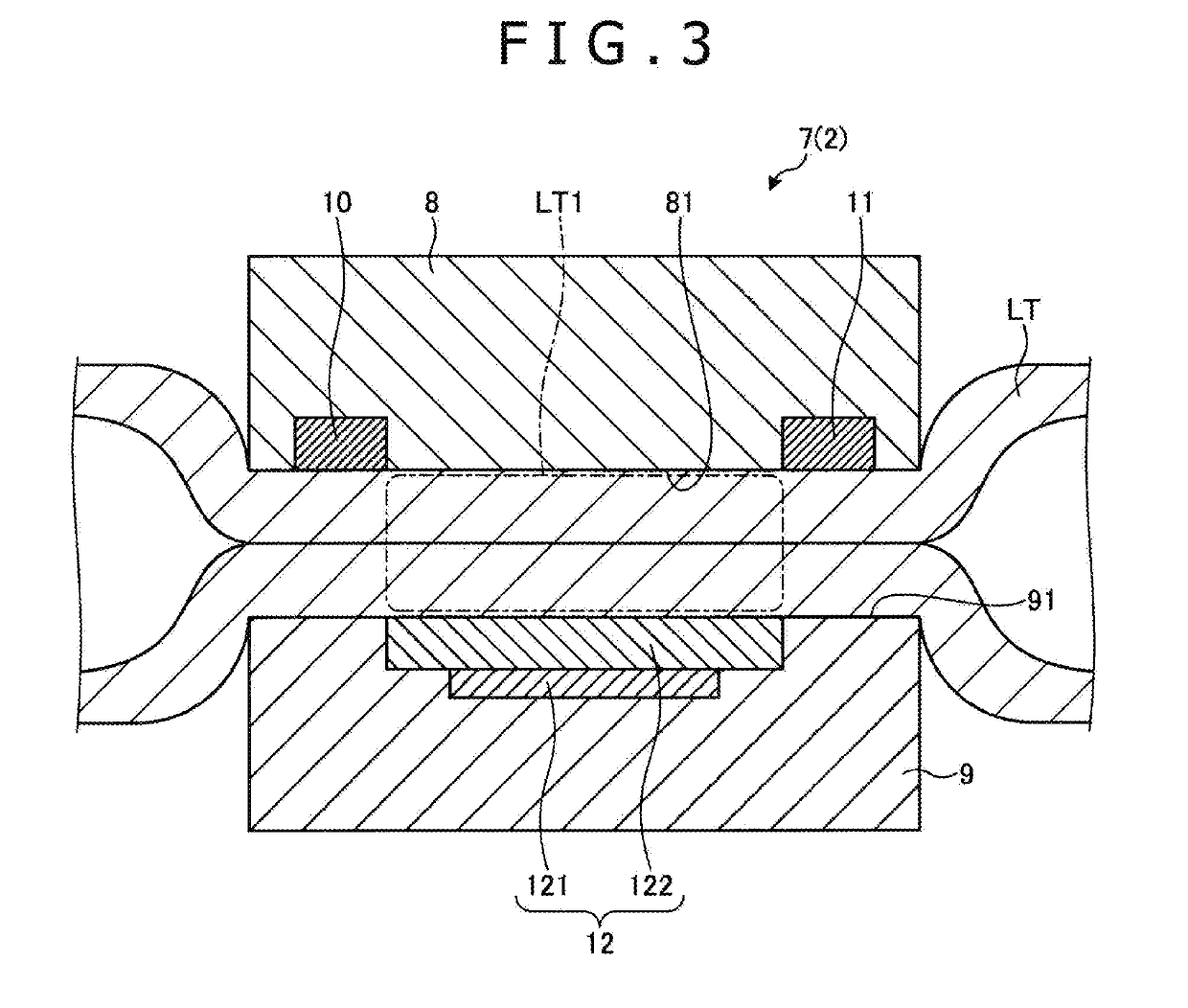
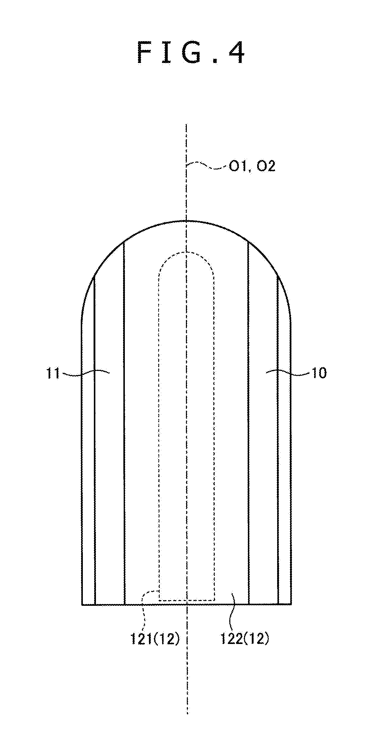
[0027]As illustrated in FIG. 1, the sheath or shaft 6 is of a substantially hollow cyli...
embodiment 2
[0080]Next, Embodiment 2 of the present disclosure will be described hereinafter.
[0081]In the description of Embodiment 2, the structural details which are similar to those of Embodiment 1 described hereinbefore are denoted by identical numeral reference and will not be described in detail or will be described briefly.
[0082]FIG. 6 is a view illustrating a grasper 7A of a treatment tool 2A according to Embodiment 2 of the present disclosure. Specifically, FIG. 6 is a cross-sectional view corresponding to FIG. 3.
[0083]As illustrated in FIG. 6, the treatment tool 2A according to Embodiment 2 is different from the treatment tool 2 (FIG. 3) described hereinbefore in Embodiment 1 as to the positions where the first and second electrodes according to the present disclosure are disposed.
[0084]As illustrated in FIG. 6, the one grasping surface 81 of the grasping jaw 8 according to Embodiment 2 is devoid of the first and second electrodes 10 and 11. Though the one grasping surface 81 accordin...
embodiment 3
[0093]Next, Embodiment 3 of the present disclosure will be described hereinafter.
[0094]In the description of Embodiment 3, the structural details which are similar to those of Embodiment 1 described hereinbefore are denoted by identical numeral reference and will not be described in detail or will be described briefly.
[0095]FIG. 7 is a view illustrating a grasper 7B of a treatment tool 2B according to Embodiment 3 of the present disclosure. Specifically, FIG. 7 is a cross-sectional view corresponding to FIG. 3.
[0096]As illustrated in FIG. 7, the treatment tool 2B according to Embodiment 3 is different from the treatment tool 2 (FIG. 3) described hereinbefore in Embodiment 1 as to the positions where the first and second electrodes according to the present disclosure are disposed and the process by which they are formed.
[0097]As illustrated in FIG. 7, the one grasping surface 81 of the grasping jaw 8 according to Embodiment 3 is devoid of the first and second electrodes 10 and 11 and...
PUM
 Abstract
Description
Claims
Application Information
 - R&D
- Intellectual Property
- Life Sciences
- Materials
- Tech Scout
- Unparalleled Data Quality
- Higher Quality Content
- 60% Fewer Hallucinations
Browse by: Latest US Patents, China's latest patents, Technical Efficacy Thesaurus, Application Domain, Technology Topic, Popular Technical Reports.
© 2025 PatSnap. All rights reserved.Legal|Privacy policy|Modern Slavery Act Transparency Statement|Sitemap|About US| Contact US: help@patsnap.com


