Method for collecting a desired blood component and performing a photopheresis treatment

a blood component and photopheresis technology, applied in the direction of positive displacement liquid engine, prosthesis, centrifuge, etc., can solve the problems of affecting the treatment effect of patients, requiring several hours to treat patients or obtain a sufficient supply of separated blood fragments, and complex systems to manufactur

Active Publication Date: 2009-01-20
MALLINCKRODT HOSPITAL PRODUCTS IP LTD
View PDF328 Cites 45 Cited by
  • Summary
  • Abstract
  • Description
  • Claims
  • Application Information

AI Technical Summary

Benefits of technology

[0008]An object of the present invention is to provide an improved method for separating a fluid, such as blood or other biological fluid, into its components. An additional object is to increase the efficiency of current fluid separation processes by decreasing the time necessary to separate out a desired amount of a fluid component from the fluid. Yet other objects of the present invention are to treat a patient more efficiently, to improve a photopheresis process, or to improve a platelet removal process. An additional object of the present invention is to separate and remove targeted cells by their specific gravity. Another object of the present invention is to eliminate the need to perform fluid separation processes in “batch” form. A still further object of the present invention is to increase the percent yield of a desired fluid component from a fluid being separated.
[0009]The present invention solves the inadequacies of the prior art by being able to continuously separate fluid components without interrupting the process to empty a centrifuge bowl and remove a separated component. Thus, the present invention eliminates batch processing and other Latham bowl batch-type techniques. These objects and others are met by the present invention which is directed at improving the methods for separating whole blood into its components and collecting a desired blood component. Depending on the intended treatment, the desired blood component may be buffy coat, red blood cells, plasma, or any component thereof. The present invention is also directed at improving existing methods of treating diseases using photopheresis therapies. Specifically, the present invention provides a continuous process for whole blood separation of sufficient fragment for photopheresis treatment so as to greatly reduce the photopheresis treatment time for a patient.
[0011]By withdrawing the red blood cells and the plasma at rates so that the buffy coat is allowed to build up within the separator, which is preferably a centrifuge bowl, the buffy coat is subjected to the centrifugal force of the separator for a prolonged period of time. Increasing the time which the buffy coat is subjected to centrifugal force yields a cleaner fraction of buffy coat and an increased white blood cell yield. Additionally, this prolonged exposure can be used to further separate the buffy coat into its constituent parts, including platelets and various kinds of leukocytes.
[0012]When pumping the mixture of whole blood and anticoagulant fluid into the separator, it is preferred that the mixture pass through, and be routed by, a cassette for controlling fluid flow. It is further preferable that the buffy coat be collected from the separator by discontinuing the withdrawal of red blood cells from the second outlet, thereby causing the red blood cells to push the buffy coat out of the separator via the first outlet as whole blood continues to enter the separator. The withdrawn buffy coat can be collected in a treatment bag that is fluidly connected to the separator via an outlet line. In this embodiment, the collection of buffy coat is preferably discontinued when red blood cells are detected in the outlet line. This will minimize red blood cells from being mixed with the desired buffy coat.
[0021]Finally, an effective method of collecting red blood cells is achieved by another aspect of the invention which is a method of collecting a desired blood component comprising: providing a separator having an inlet, a first outlet, and a second outlet; drawing whole blood from a source; adding an anticoagulant fluid to the whole blood in a predetermined ratio to form a mixture of whole blood and anticoagulant fluid; pumping the mixture of whole blood and anticoagulant fluid into the separator via the inlet at a selected inlet rate; separating the mixture into blood components of different densities; withdrawing plasma and buffy coat from the separator while continuing to pump the mixture of whole blood and anticoagulant fluid into the separator, the plasma and buffy coat being withdrawn at rates so as to build up red blood cells in the separator, the plasma and buffy coat being withdrawn via the first outlet; and upon a predetermined amount of red blood cells building up in the separator, collecting the red blood cells from the separator via the second outlet. This method allows the red blood cells to build up in the separator and be subjected to a maximum amount of prolonged centrifugal force

Problems solved by technology

However, a major drawback to the Latham bowl separator is that the separation process must be repeatedly stopped to remove the packed RBCs and plasma once they fill the inside of the bowl, creating a “batch-type” treatment process.
Although the Latham bowl separator has a high volume yield, the constant filling and emptying of this bowl wastes time; thus, the process is considered less efficient with respect to time.
Prior photopheresis and apheresis systems and methods usually require batch processes and therefore take several hours to treat a patient or to obtain a sufficient supply of separated blood fragments.
Furthermore, the systems are very complex to manufacture.

Method used


Image

  • Method for collecting a desired blood component and performing a photopheresis treatment
  • Method for collecting a desired blood component and performing a photopheresis treatment
  • Method for collecting a desired blood component and performing a photopheresis treatment

Examples


Embodiment Construction

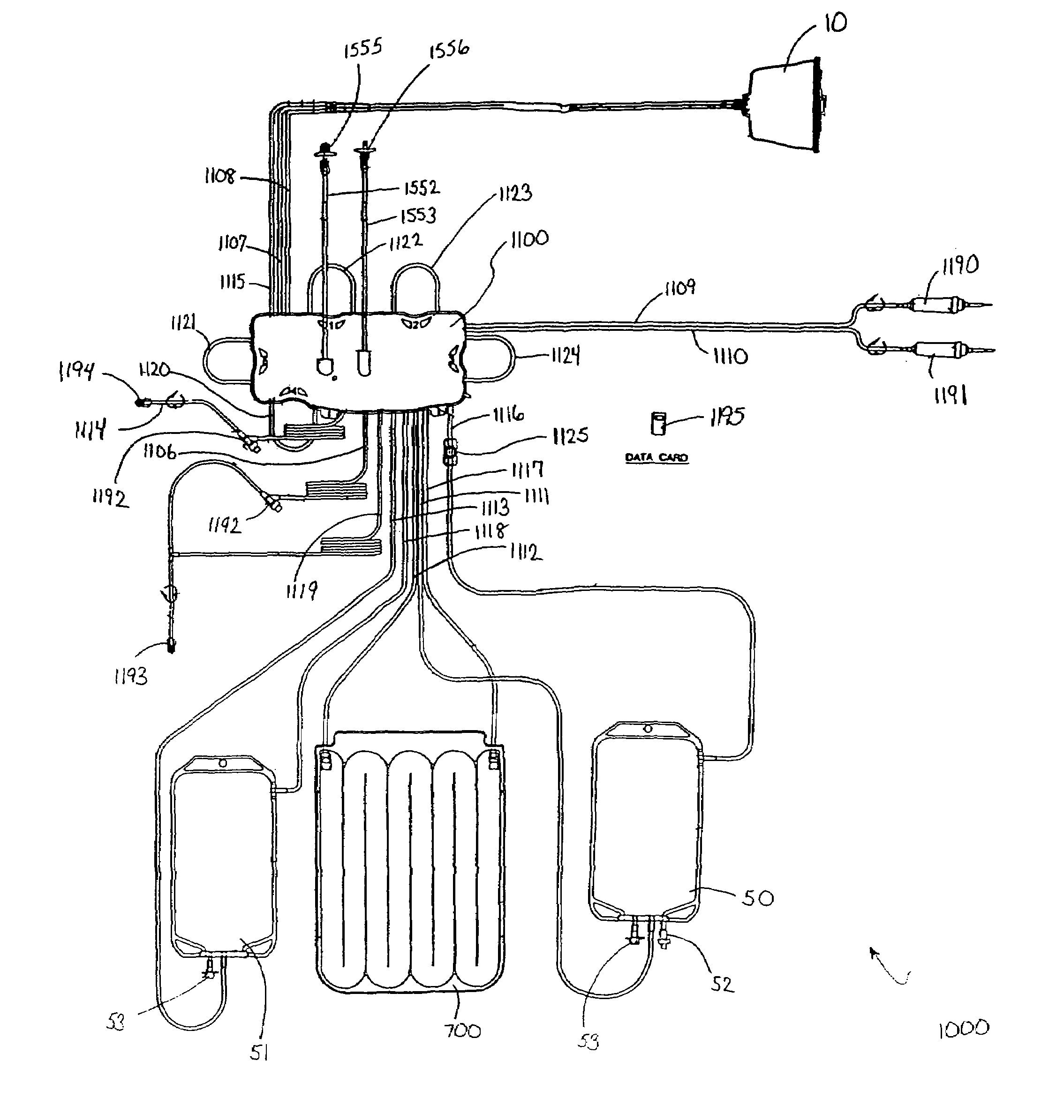
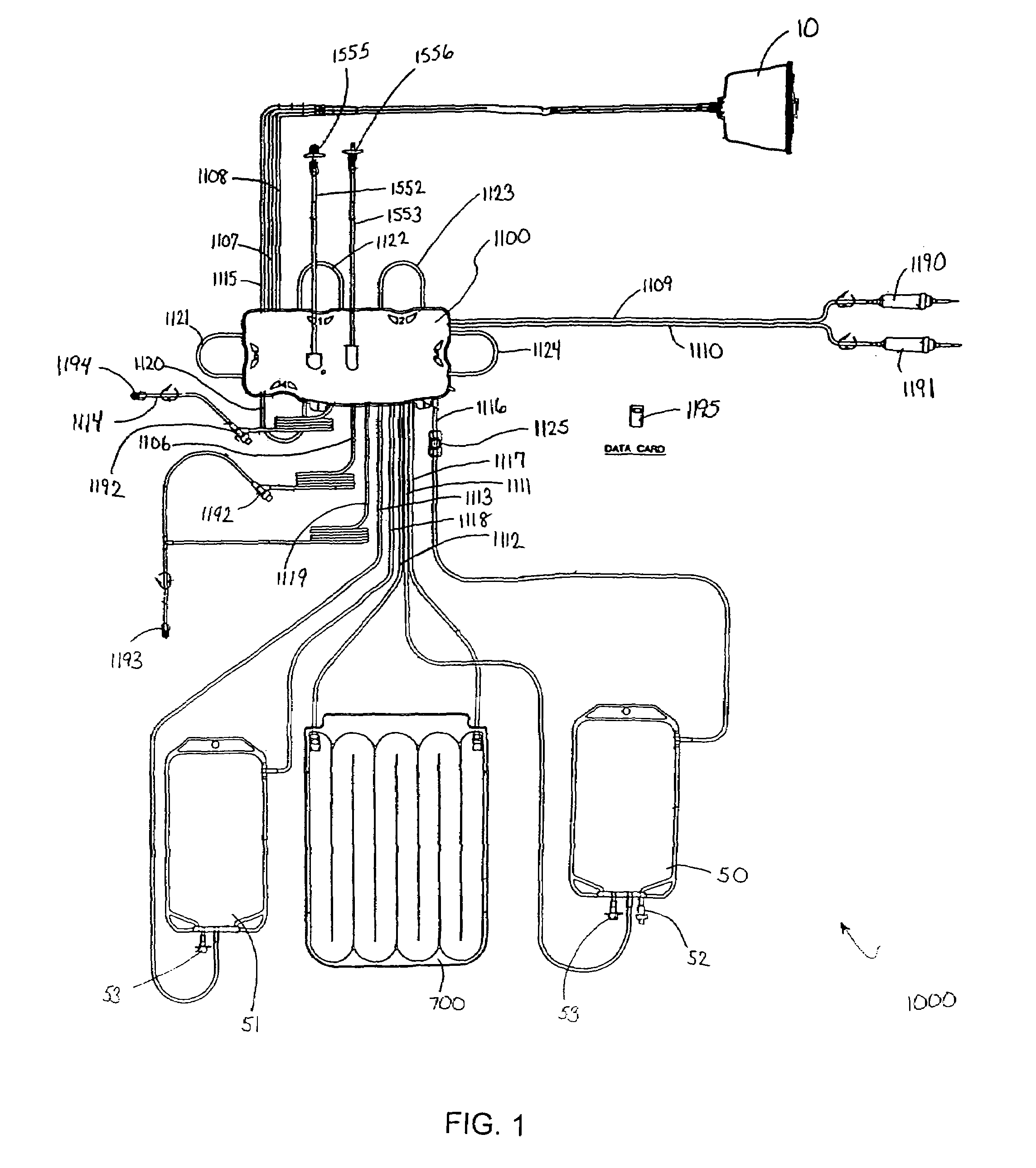
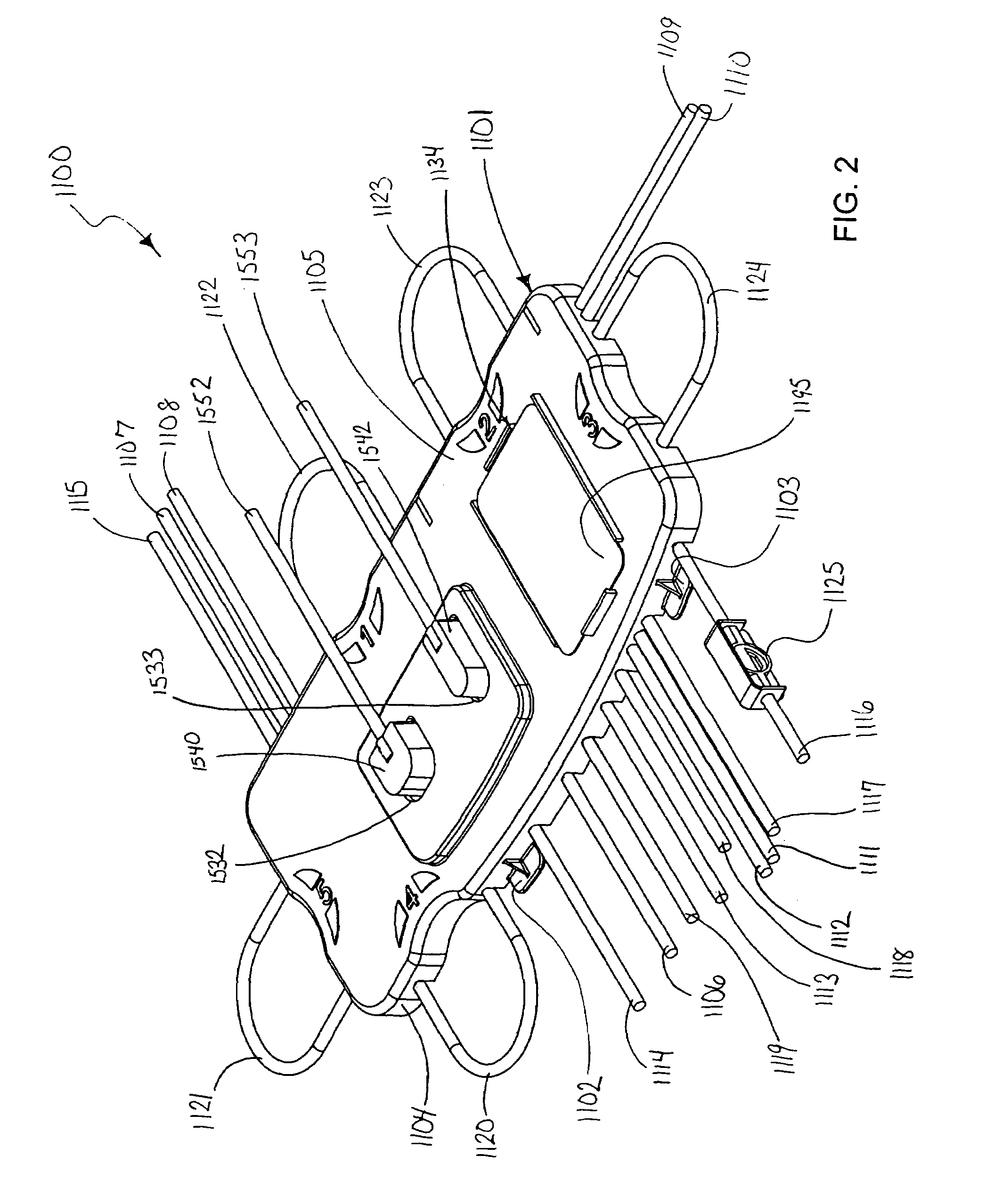
[0080]Features of the present invention are embodied in the permanent blood driving equipment, the disposable photopheresis kit, the various devices which make up the disposable kit, and the corresponding treatment process. The following written description is outlined as follows:

[0081]I. Disposable Photopheresis Kit[0082]A. Cassette for Controlling Fluid Flow[0083]1. Filter Assembly[0084]B. Irradiation Chamber[0085]C. Centrifuge Bowl[0086]1. Drive Tube

[0087]II. Permanent Tower System[0088]A. Photoactivation Chamber[0089]B. Centrifuge Chamber[0090]C. Fluid Flow Control Deck[0091]1. Cassette Clamping Mechanism[0092]2. Self-Loading Peristaltic Pumps[0093]D. Infra-Red Communication

[0094]III. Photopheresis Treatment Process

[0095]The above-outline is included to facilitate understanding of the features of the present invention. The outline is not limiting of the present invention and is not intended to categorize or limit any aspect of the invention. The inventions are described and illu...


PUM

PropertyMeasurementUnit
treatment timeaaaaaaaaaa
pore sizeaaaaaaaaaa
wavelengthaaaaaaaaaa

Abstract

An improved method for separating whole blood into components and collecting a desired blood component. The method allows a desired blood component to be subjected to centrifugal forces within a separator for prolonged periods of time, yielding a cleaner cut and higher yield of the desired blood component. Whole blood is drawn from a source and pumped into a separator, the undesired blood components are removed from the separator at rates so as to build up the desired blood component in the separator. The desired blood component is only removed after a predetermined amount of the desired blood component has built up in the separator. It is preferred that the desired blood component be buffy coat and that the method be used to perform photopheresis treatments. In another aspect, the invention is a method of performing a full photopheresis treatment to treat diseases in a reduced time, preferably less than about 70 minutes, and more preferably less than about 45 minutes.

Description

CROSS-REFERENCE TO RELATED APPLICATIONS[0001]This application is a continuation-in-part application of U.S. patent application Ser. No. 10 / 375,629, filed Feb. 27, 2003 now U.S. Pat No. 7,186,230, which claims the benefit of U.S. Provisional Application, Ser. No. 60 / 361,287, filed Mar. 4, 2002, both of which are hereby incorporated by reference in their entireties.TECHNICAL FIELD OF THE INVENTION[0002]The present invention relates generally to methods for separating whole blood into blood components and collecting a desired blood component, and specifically to methods of treating diseases with a photopheresis treatment.BACKGROUND OF THE INVENTION[0003]Several treatments for disease require the removal of blood from a patient, processing the one or more components of the blood, and return of the processed components for a therapeutic effect. Those extracorporeal treatments require systems for safely removing blood from the patient, separating it into components, and returning the bloo...

Claims


Application Information

Patent Timeline
Patent Type & Authority Patents(United States)
IPC IPC(8): A61M37/00A61M1/02A61M1/00A61M1/10A61M1/36B04B5/04F04B43/12F16L33/00F16L39/02
CPCA61K41/0066A61M1/3696A61M1/3681A61M1/3693B04B5/0442F04B43/1253A61M1/0058A61M1/3686A61M1/361A61M1/3683A61M2202/0427A61M2205/051A61M2205/053A61M2205/12A61M2205/125A61M2205/35A61M2205/3569A61M2205/52A61M2205/60A61M2205/75B04B2005/0464B04B2005/0492F28F2260/02A61M2202/0092A61M1/0227A61M1/3603A61M1/77A61M3/0201A61M1/72A61M1/362264A61M1/36224A61M1/362266A61M1/36225
Inventor BRIGGS, DENNIS
Owner MALLINCKRODT HOSPITAL PRODUCTS IP LTD
Why Eureka
Try Eureka