Minimum time feedback control of efficacy and safety of thermal therapies

a technology of thermal therapy and safety control, which is applied in the field of medicine and the thermal treatment of tumor tissues, can solve the problems of limiting the affecting the clinical application of thermal therapy, and unintended normal tissue damage, so as to minimize patient pain and discomfort, reduce treatment time, and reduce patient variability. the effect of patient safety

Inactive Publication Date: 2011-06-09
UNIV OF UTAH RES FOUND
View PDF6 Cites 46 Cited by
  • Summary
  • Abstract
  • Description
  • Claims
  • Application Information

AI Technical Summary

Benefits of technology

[0007]One embodiment of a control system that automatically delivers a physician-prescribed thermal dose in minimum time without violating the imposed normal tissue constraints was described by those of skill in the art as discussed in Arora et al. 2005a, Arora et al. 2005b, Arora et al. 2005c, Arora et al. 2004, Arora et al. 2003, Palussiere et al. 2003, Arora et al. 2002 and Arora et al. 2006, all of which are incorporated herein by reference. Compared to the traditional approach, a real-time automatic feedback treatment control system would offer a number of advantages, including but not limited to: (1) robustness with respect to patient-to-patient variability and various treatment disturbances, such as changes in temperature-dependent ultrasound absorption and tissue perfusion; (2) normal tissue safety; (3) direct control of the thermal dose; and (4) reduced treatment time. As such, it would be desirable to provide an automatic thermal treatment control system that delivers a desired thermal dose distribution to the target tissue in a minimum time without causing healthy tissue damage and minimize patient pain and discomfort.

Problems solved by technology

The lack of adequate control of thermal therapies results in long treatment times, incomplete treatment of large targets, and unintended normal tissue damage, thus impedes a broader penetration of thermal therapies into clinical practice.

Method used


Image

  • Minimum time feedback control of efficacy and safety of thermal therapies
  • Minimum time feedback control of efficacy and safety of thermal therapies
  • Minimum time feedback control of efficacy and safety of thermal therapies

Examples


example 1

Phantom Results

[0044]The objective was to deliver Df=10 CEM43° T40 to the selected target region while limiting the temperature at the constraint location to below 6.5° C. A low thermal dose was selected to reduce time and the associated cost required to complete multiple experimental runs. The ultrasound power was constrained (umax=11 W) to reflect hardware limitations and to avoid cavitation.

[0045]The controller tuning parameters were set as follows: prediction horizon, p=4.6;

[0046]control horizon, m=2.3 seconds; and the moving treatment horizon, tTH=4.6 seconds. The treatment horizon was selected to: (a) force the activation of the transducer power constraint at the beginning of the treatment when the normal tissue temperature constraint was not active, and (b) towards the end of the treatment, to ensure that the thermal dose controller, KD, generates an almost attainable reference temperature trajectory to minimize overdosing of the target.

[0047]FIG. 3 depicts the evolution of t...

example 2

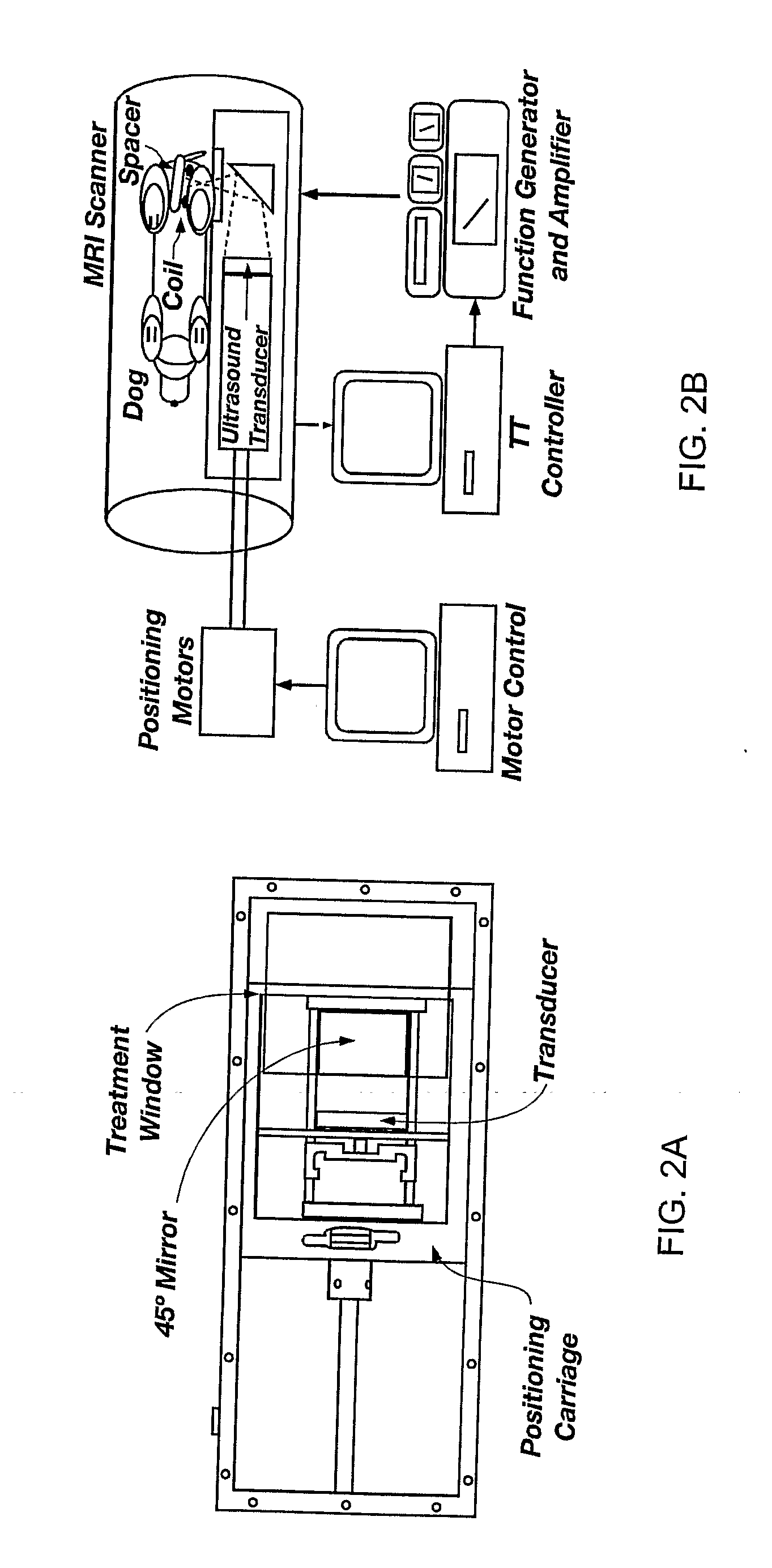
In Vivo Canine Results

[0050]The in vivo results were obtained with the ultrasound power constrained to umax=14 W. The desired final thermal dose was set to 20 CEM. Compared to the Example 1 phantom case, a tighter and clinically more realistic normal tissue constraint of 5.5° C. was imposed in the close proximity of the target. By minimizing tissue damage, it was possible to perform multiple tests with the same subject and evaluate the effect of various factors on the performance of the automatic treatment control system.

[0051]FIG. 4 depicts the controller-generated power, MR temperature measurements, and the resulting thermal dose for one of the test runs. The controller tuning parameters p and in were set to 24 and 12 seconds, respectively. The value of the moving treatment horizon, tTH, was set to 24 seconds, which forced the activation of the transducer constraint at the beginning of the treatment. Because of a slower sampling of MR-thermometry measurements during in vivo experi...

example 3

Automatic Control of Focal Trajectory and Intensity of Ultrasound Phased Arrays

[0062]A prototype treatment control system that automatically selects location and intensity of the ultrasound focal zone to deliver the prescribed thermal dose to the target in minimum time without violating explicitly imposed normal tissue safety constraints is developed. The results of its initial evaluation in a computer-simulated treatment of a realistic three-dimensional breast cancer patient are reported in Niu et al. 2006. These results illustrate salient features of the developed prototype, which are necessary to minimize the treatment duration while simultaneously satisfying the normal tissue safety constraints.


PUM


Abstract

A thermal treatment control system including an imaging device for specifying the geometry and/or location of the treatment target, a thermal energy element for applying a thermal treatment for the heating or cooling of a target tissue for therapeutic purposes, a thermal energy detecting element for detecting a measured tissue response to the thermal treatment and a feedback controller for a real-time modification of the intensity and spatial distribution of the thermal dose in order to achieve therapeutic efficacy over a minimum or reduced treatment time while satisfying treatment constraints imposed to limit damage to normal tissues.

Description

PRIORITY CLAIM[0001]This application claims the benefit under 35 U.S.C. §119(e) of U.S. Provisional Patent Application Ser. No. 60 / 726,673, filed Oct. 14, 2005, for “MINIMUM TIME FEEDBACK CONTROL OF EFFICACY AND SAFETY OF THERMAL THERAPIES,” the entire contents of which are hereby incorporated herein by this reference.STATEMENT REGARDING FEDERALLY SPONSORED RESEARCH OR DEVELOPMENT[0002]This invention was made with government support under grant #NCI-R01-CA33922 awarded by the National Institutes of Health, and under grant #CTS 0117300 awarded by the National Science Foundation. The Government has certain rights to this invention.TECHNICAL FIELD[0003]The present invention relates generally to medicine and the thermal treatment of tumor tissues. More particularly, the invention relates to methods and apparatus of a treatment control system for invasive and noninvasive heating or cooling of target tissues for therapeutic purposes using ultrasound (US), radiofrequency (RF), microwave or...

Claims


Application Information

Patent Timeline
Patent Type & Authority Applications(United States)
IPC IPC(8): A61B5/055A61B18/00
CPCA61B19/22A61B2017/00084A61N2007/025A61N7/02A61B2019/5236A61B34/70A61B2090/374
Inventor SKLIAR, MIKHAILROEMER, ROBERTARORA, DHIRAJ
Owner UNIV OF UTAH RES FOUND
Why Eureka
Try Eureka