
Back Scratcher

a back scratcher and scratching technology, applied in the field of back scratchers, can solve the problems of providing an unsatisfactory scratching sensation, too hard in one direction, too hard in the other direction, etc., and achieve the effect of convenient gripping and facilitating the scratching of various body parts

Inactive Publication Date: 2017-02-16
KELNHOFER DENNIS MICHAEL
View PDF1 Cites 8 Cited by
  • Summary
  • Abstract
  • Description
  • Claims
  • Application Information

AI Technical Summary

Benefits of technology

The present invention is a back scratcher that includes a scratcher head with sharp teeth for scratching various body parts, an elongated shaft to reach the body parts, and a looped handle for easy gripping or hanging on a hook for storage. The technical effect of the invention is to provide a convenient and efficient tool for scratching the back, which can be easily stored when not in use.

Problems solved by technology

All of these variations have one or more flaws that render them ineffective to some degree.
A common problem is found in U.S. Pat. No. 6,830,552 issued to Gonzalez and U.S. Pat. No. 7,037,016 issued to Nelson, both of which use a simulated human hand as the scratching device.
Because this creates such a small scratching area, it provides an unsatisfactory scratching sensation.
Each of these examples again use the simulated human hand, but present an additional problem.
Many times, the angle of the fingers causes the device to scratch too hard in one direction and not hard enough in the other direction.
However, this device presents a new problem.
This could be cumbersome or dangerous if left lying somewhere other than up on a shelf, desk, etc.
Several back scratchers are rendered ineffective by their shape or extraneous purpose.
It achieves this goal, but is not effective as a backscratcher because it is too short to reach the back and too bulky to be inserted under a shirt.
This bulkiness problem also exists with the back scratchers presented in U.S. Pat. No. 4,574,788 issued to Jordan and U.S. Pat. No. 7,037,016 issued to Nelson.
Both would be awkward to insert under a garment.
Another problem with two previously patented back scratchers exists in the type of handle used.
The problem with the telescoping handle of these back scratchers is their tendency to wear down and become loose and therefore too easily contracted.
When the handle becomes too loose, the back scratcher is rendered useless because the scratching device can not be moved across the skin with sufficient pressure.
Another problem is seen in U.S. Pat. No. 869,250 issued to Martin.
This creates a problem when a corn cob is not readily available and another appropriate material must be used.

Method used


Image

  • Back Scratcher
  • Back Scratcher
  • Back Scratcher

Examples


Embodiment Construction

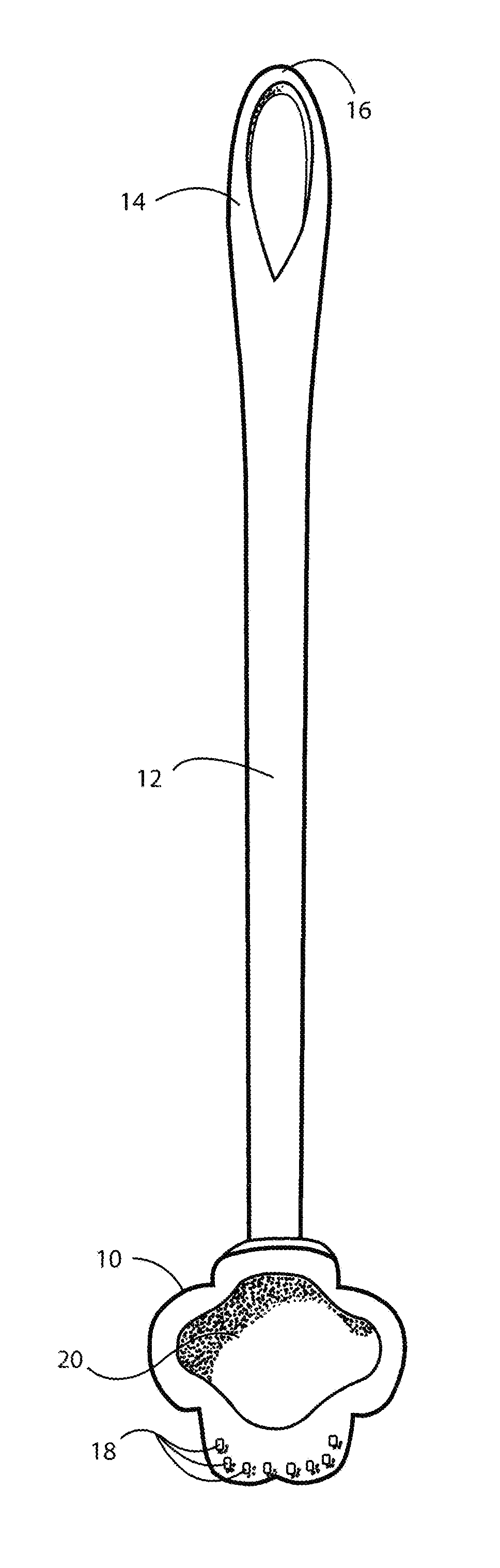
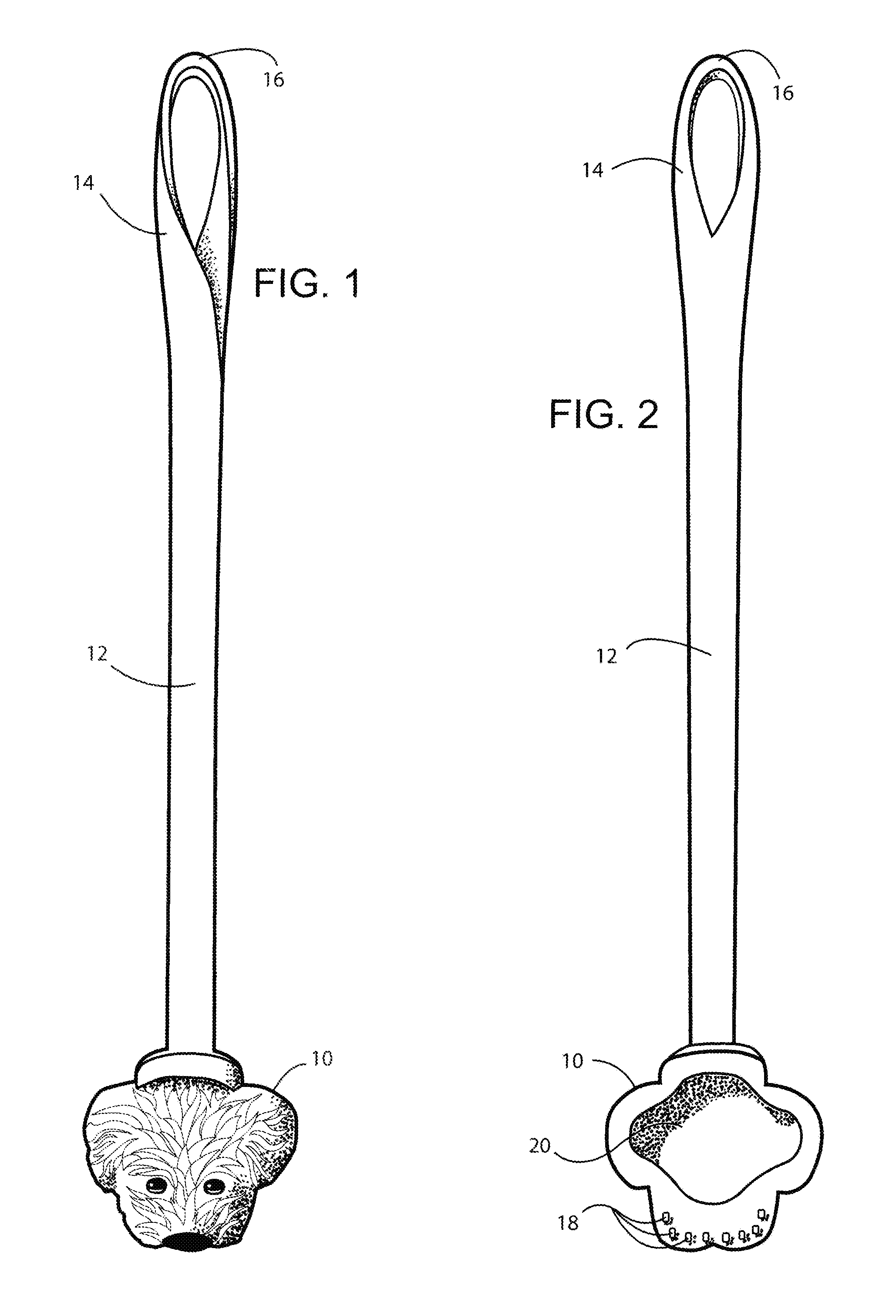
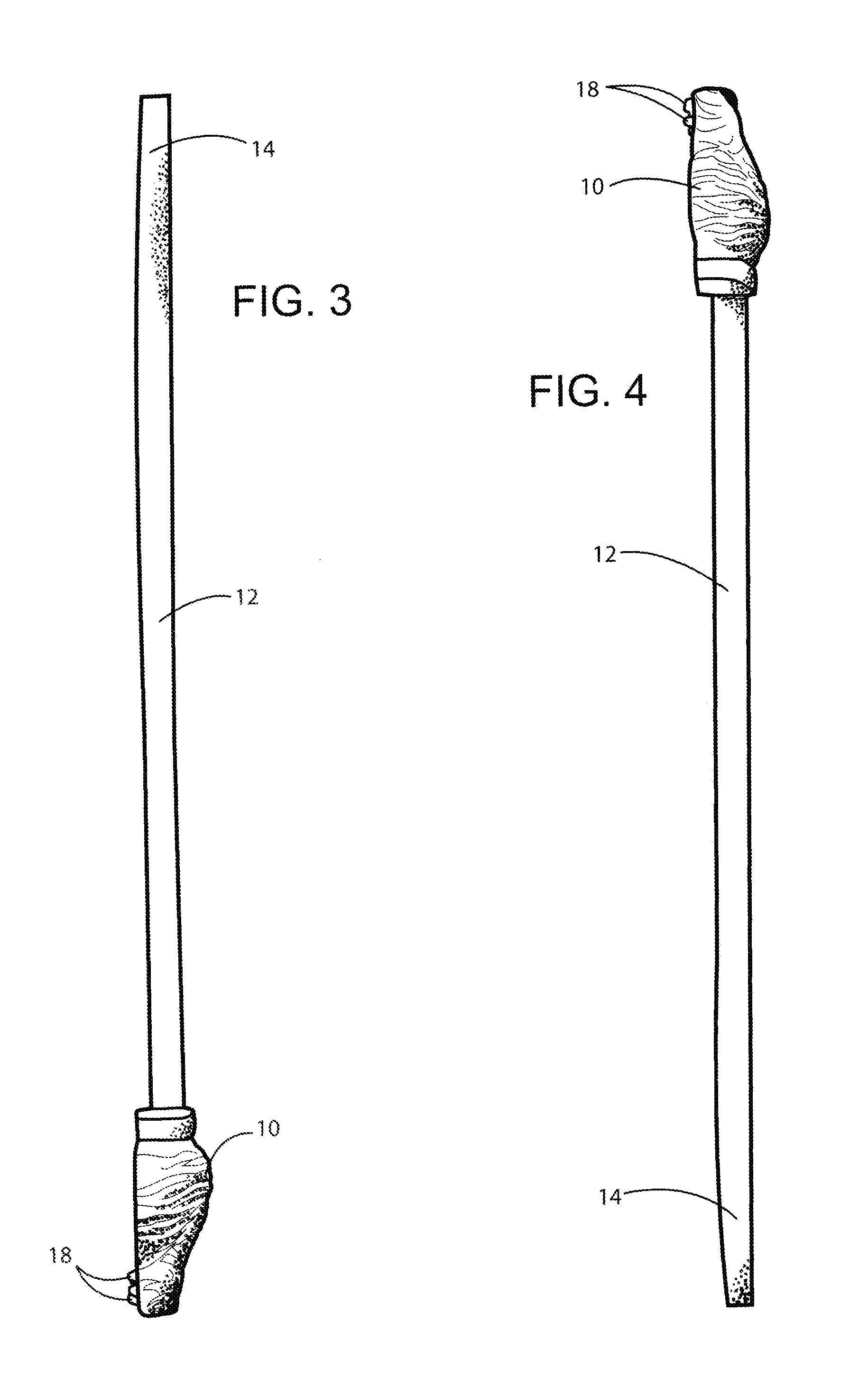
[0035]FIG. 1 shows the preferred embodiment of the back scratcher. It is comprised of a scratcher head 10 connected to a shaft 12 which extends in a straight line at the end of which is located a handle 14. The handle contains a hollowed-out elliptical hole forming a hanger loop 16 which serves as a means of storing the back scratcher on a hook or push pin.

[0036]FIG. 2 shows the bottom view of the back scratcher revealing the underside of the scratcher head. Located on the underside of the scratcher head in close proximity to the front end of the back scratcher are the scratching teeth 18. The preferred embodiment of this invention would contain 8 scratching teeth forming an arc following the rounded contour at the front of the scratcher head. FIG. 2 shows a recessed cavity 20 which is formed by hollowing out a portion of the underside of the scratcher head to reduce its weight and give more balance to the back scratcher. The preferred overall length of the back scratcher is between...


PUM


Abstract

A back scratcher which includes (a) a scratcher head containing a plurality of scratching teeth on its underside, projecting outward at a right angle to the plane of the scratcher head and being a consistent length to provide an even scratching surface; (b) an elongated shaft with a first end connected to the back of the scratcher head opposite the scratching teeth and a second end connected to (c) a handle which forms a loop to provide a means for gripping and hanging for storage.

Description

CROSS-REFERENCE TO RELATED APPLICATIONS[0001]Not ApplicableFEDERALLY SPONSORED RESEARCH[0002]Not ApplicableSEQUENCE LISTING OR PROGRAM[0003]Not ApplicableBACKGROUND OF THE INVENTION[0004]Field of Invention[0005]This invention relates to back scratchers, specifically to such devices which are used for the relief of itching of the back and other body parts of humans and / or their pets.[0006]Prior Art[0007]Many devices exist for the relief of itching on parts of the body not easily reached with one's fingernails. It can be imagined that the earliest consisted of an altered branch from a tree and now the contemporary standard is the ubiquitous plastic simulated mini human hand at the end of a long handle. There are also many variations made of bamboo, wood or other material that can be purchased. All of these variations have one or more flaws that render them ineffective to some degree.[0008]A common problem is found in U.S. Pat. No. 6,830,552 issued to Gonzalez and U.S. Pat. No. 7,037,0...

Claims


Application Information

Patent Timeline
Patent Type & Authority Applications(United States)
IPC IPC(8): A61H7/00
CPCA61H7/003A61H2201/1692
Inventor KELNHOFER, DENNIS MICHAEL
Owner KELNHOFER DENNIS MICHAEL
Learn More