Reconfigurable diverter conveyor

Active Publication Date: 2017-02-16
STACKER
View PDF5 Cites 1 Cited by
  • Summary
  • Abstract
  • Description
  • Claims
  • Application Information

AI Technical Summary

Benefits of technology

The present disclosure addresses the problem of providing a conveyor that can carry sheets of material from one end to the other, by using two drive wheel assemblies and two idler wheel assemblies that are independently positioned. This allows for better control and efficiency in the conveyor's operation. The conveyor includes a motion converter that converts rotary motion into linear motion, which is connected to the drive wheel brackets or idler wheel brackets to provide the necessary power to the conveyor. The technical effects of this invention include improved speed, accuracy, and efficiency in the conveyor's operation.

Problems solved by technology

Manually repositioning the ends of the belts of the transfer conveyor can be time consuming, and it may sometimes be difficult to ensure that a given spacing of the belt ends can be repeated accurately each time a particular product is processed.

Method used


Image

  • Reconfigurable diverter conveyor
  • Reconfigurable diverter conveyor
  • Reconfigurable diverter conveyor

Examples


Embodiment Construction

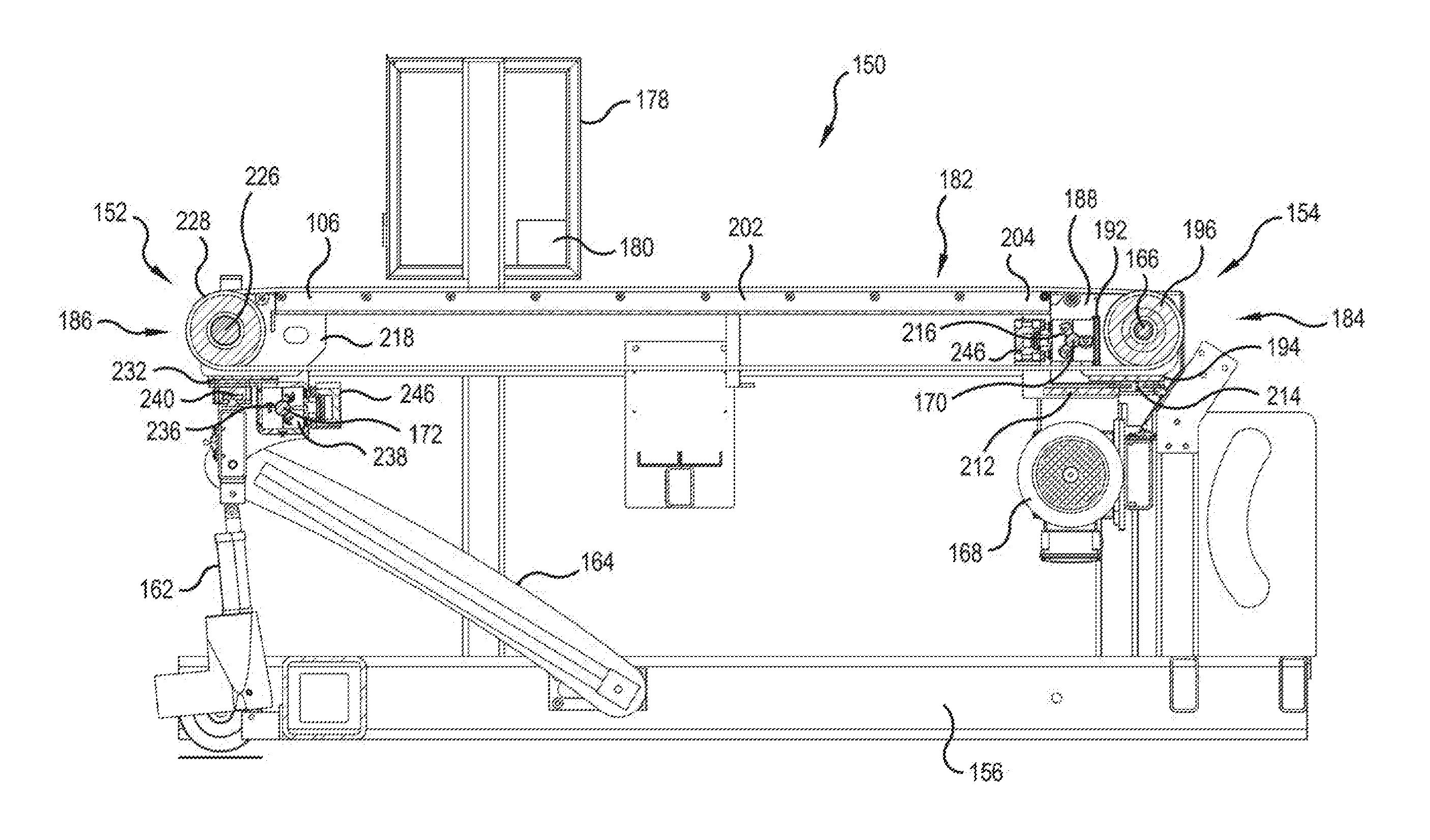
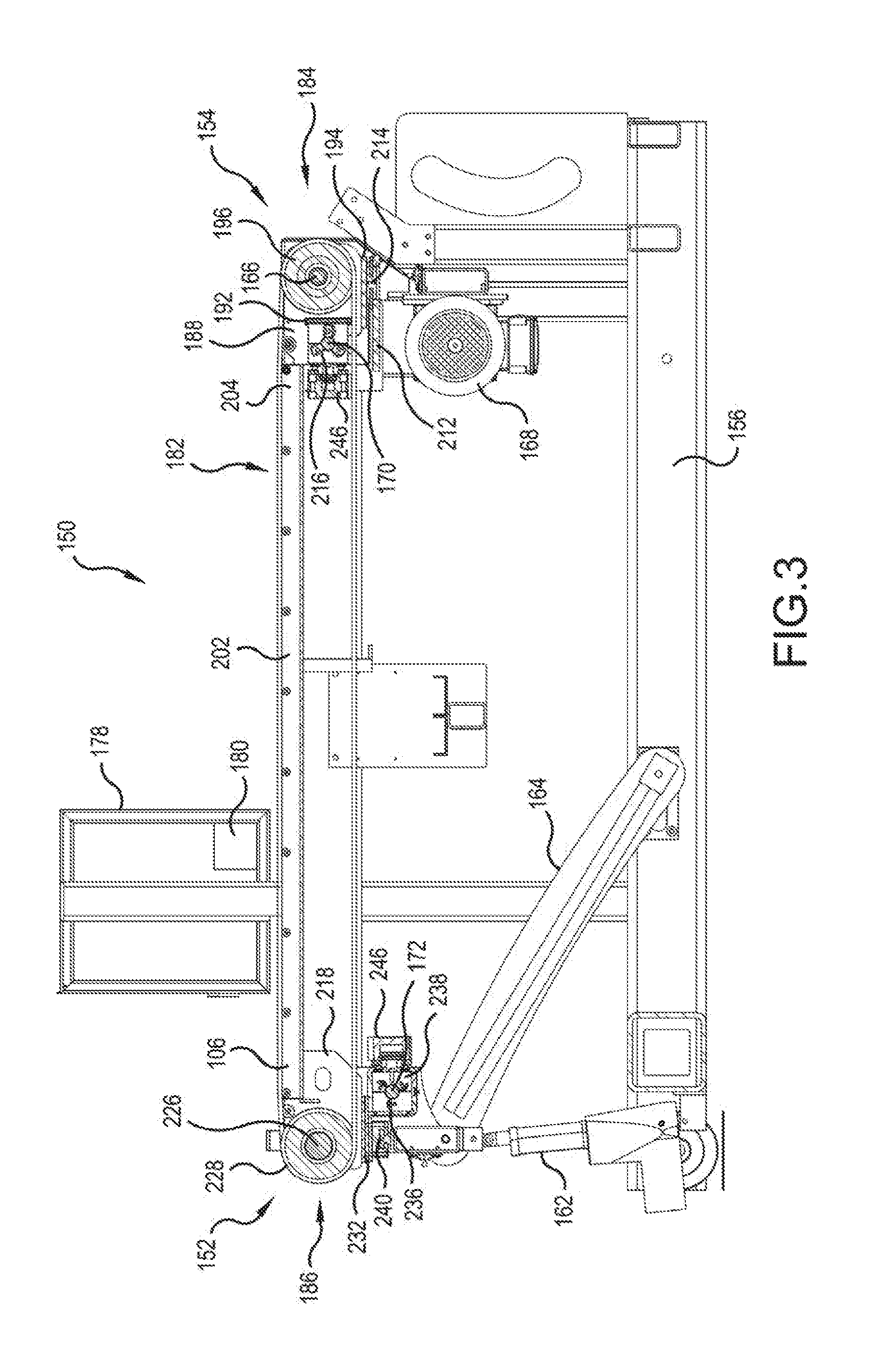
[0021]Referring now to the drawings, wherein the showings are for purposes of illustrating presently preferred embodiments of the invention only and not for limiting same, FIGS. 3 and 4 show a transfer conveyor 150 having a longitudinal centerline 151, an entry end 152 and a discharge end 154 and a frame including a bottom support 156, a first side portion 158 and a second portion 160. An electric actuator with feedback 162 is connected between the bottom support 156 and the entry end 152 of the transfer conveyor 150 and configured to raise and lower the entry end 152. This allows the entry end 152 to be positioned correctly relative to the location of the output of a layboy conveyor which feeds sheets of material to the transfer conveyor 150. A swing arm 164 is connected between the bottom support 156 and the frame. The angle through which the swing arm 164 can pivot is limited so that the swing arm 164 forms a hard stop and prevents the entry end 152 from dropping below a predeter...


PUM

PropertyMeasurementUnit
Forceaaaaaaaaaa

Abstract

A conveyor includes a plurality of belt support assemblies each having a drive wheel assembly at one end and an idler wheel assembly at the other end. Each of the drive and idler wheel assemblies includes a motion converter for converting the rotational movement of a shaft into linear motion along the shaft and an actuator for selectively engaging the motion converter and the shaft. A controller controls the operation of the shafts and the actuators to selectively and individually control the location of each end of each belt assembly relative to one another and to a centerline of the conveyor.

Description

CROSS-REFERENCE TO RELATED APPLICATIONS[0001]The present application claims the benefit of U.S. provisional patent application No. 62 / 204,091, filed Aug. 12, 2015, the entire contents of which is hereby incorporated by reference.FIELD OF THE INVENTION[0002]The present invention is directed to a conveyor having a plurality of belts, each having a first end and a second end, for transporting sheets of material in a longitudinal direction wherein the lateral position the first end of each belt is adjustable, and, more specifically, toward a conveyor having a plurality of belts, each having a first end and a second end, for transporting sheets of material in a downstream direction wherein the lateral position the first end of one of the plurality of belts is automatically adjustable independently of the first end of another one of the plurality of belts.BACKGROUND OF THE INVENTION[0003]Devices for stacking generally planar articles of material, such as sheets of corrugated material, are...

Claims


Application Information

Patent Timeline
IPC IPC(8): B65H29/60B65H43/00B65H29/16
CPCB65H29/60B65H43/00B65H29/16B65H29/18B65H29/50B65H2301/4473B65H2404/255B65H2404/2691B65H2404/2693B65H2701/1762B65H2220/01B65H2220/02
Inventor ALLEN, JR., CLARENCE C.SUNDSTROM, MICAH C.CROWE, ERIC H.ARMSTRONG, SAMANTHA L.J.
Owner STACKER
Why Eureka
Try Eureka