Method of sealing wells by squeezing sealant

a well sealing and sealant technology, applied in the direction of sealing/packing, earthwork drilling and mining, borehole/well accessories, etc., can solve the problems of inability to use conventional portland cement for squeeze cementing, and inability to squeeze cemen

Inactive Publication Date: 2017-02-16
WILD WELL CONTROL
View PDF3 Cites 20 Cited by
  • Summary
  • Abstract
  • Description
  • Claims
  • Application Information

AI Technical Summary

Benefits of technology

[0006]The present disclosure generally relates to a method of sealing wells by squeezing sealant into the annulus between the inner and outer tubular strings. In one embodiment, a method for sealing a well includes: placing an obstruction in a bore of an inner tubular string disposed in a wellbore; forming an opening th

Problems solved by technology

As a result of pressure and temperature changes, the integrity of the cement sheath can be compromised.
The use of conventional Portland cement for squeeze cementing has limitations

Method used


Image

  • Method of sealing wells by squeezing sealant
  • Method of sealing wells by squeezing sealant
  • Method of sealing wells by squeezing sealant

Examples


Embodiment Construction

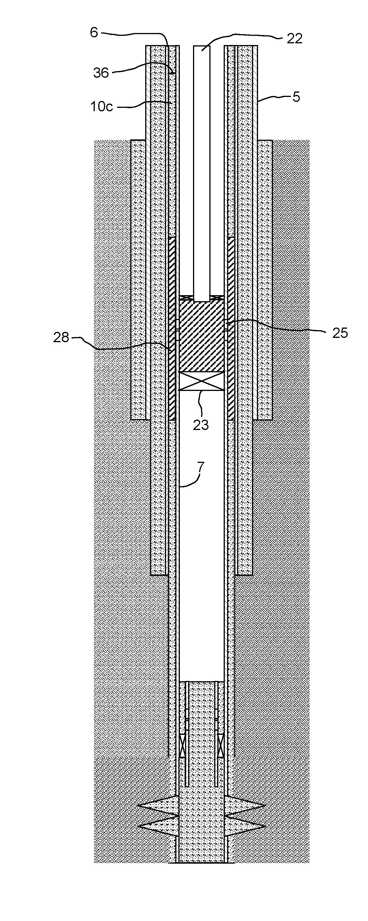
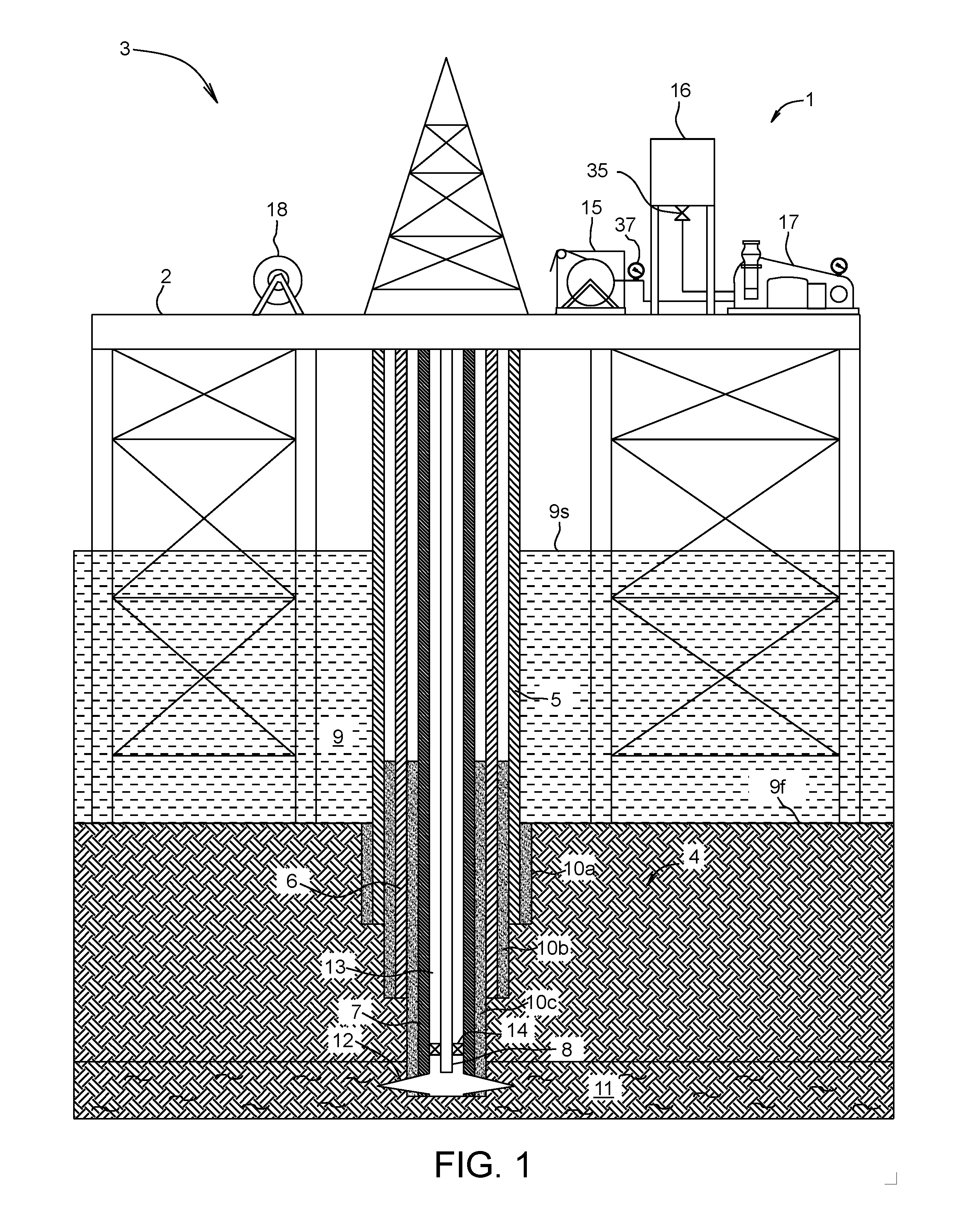
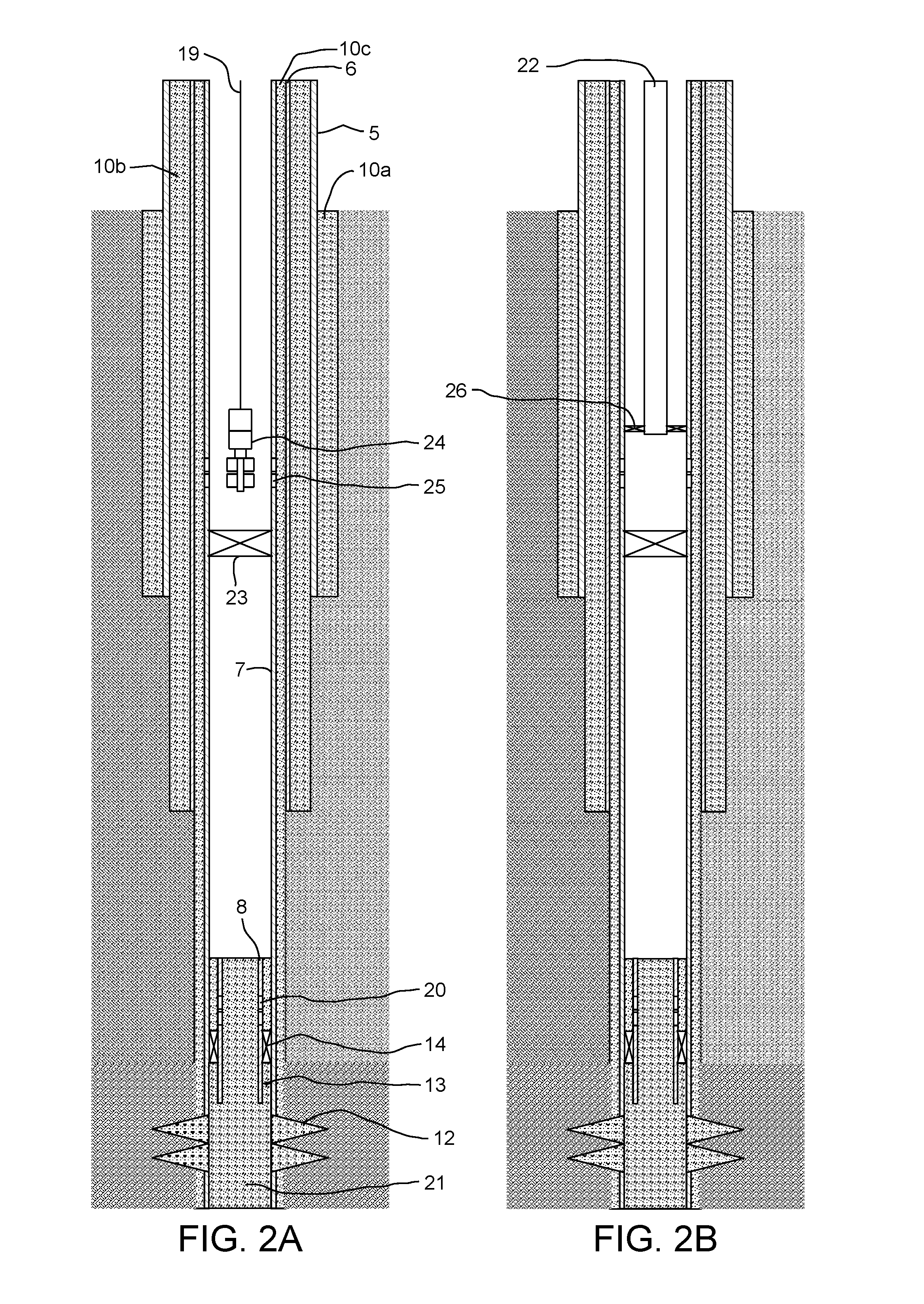
[0016]FIG. 1 illustrates an illustrative equipment package 1 used for performing the squeeze operation, and located on a platform 2, according to one embodiment of the present disclosure. The platform 2 may be part of a well 3 further including a subsea wellbore 4, a drive pipe 5, a surface casing string 6, a production casing string 7, and a production tubing string 8. The drive pipe 5 is commonly set from above a surface 9s (aka waterline) of the sea 9, through the sea, and into the seafloor 9f (aka mudline). The drive pipe 5 allows the wellhead (not shown) to be located on the platform 2 above the waterline 9s.

[0017]Once the drive pipe 5 has been set, and (if desired cemented 10a, the subsea wellbore 4 is drilled into the seafloor 9f within the envelope of the drive pipe 5. The surface casing string 6 is then run-in the drive pipe 5 and into the wellbore 4 and cemented into place by forming a cement sheath 10b. When the wellbore 4 reaches a hydrocarbon-bearing formation 11, i.e....


PUM


Abstract

A method for sealing a well includes: placing an obstruction in a bore of an inner tubular string disposed in a wellbore; forming an opening through a wall of the inner tubular string above the obstruction; mixing a resin and a hardener to form a sealant; and squeezing the sealant into the bore, through the opening, and into an annulus formed between the inner tubular string and an outer tubular string, thereby repairing a cement sheath present in the annulus.

Description

BACKGROUND OF THE DISCLOSURE[0001]Field of the Disclosure[0002]The present disclosure generally relates to a method of sealing wells by squeezing a sealant into an annulus thereof.[0003]Description of the Related Art[0004]The hard impermeable sheath deposited in the annular space in a well by primary cementing is subjected to a number of stresses during the lifetime of the well. The pressure inside the casing can increase or decrease as the fluid filling it changes or as additional pressure is applied to the well, such as when the drilling fluid is replaced by a completion fluid or by a fluid used in a stimulation operation. A change of temperature also creates stress in the cement sheath, at least during the transition period before the temperatures of the steel and the cement come into equilibrium. As a result of pressure and temperature changes, the integrity of the cement sheath can be compromised. Thus, it can become necessary to repair the primary cement sheath, such as during...

Claims


Application Information

Patent Timeline
IPC IPC(8): E21B33/14E21B33/12
CPCE21B33/12E21B33/14
Inventor SABINS, FREDMEADE, CLIFTONBROWN, DAVIDWATTERS, JEFFREYLEAL, JORGE ESTEBAN
Owner WILD WELL CONTROL
Why Eureka
Try Eureka