

Equatorial Stitching of Hemispherical Images in a Spherical Image Capture System
- Summary
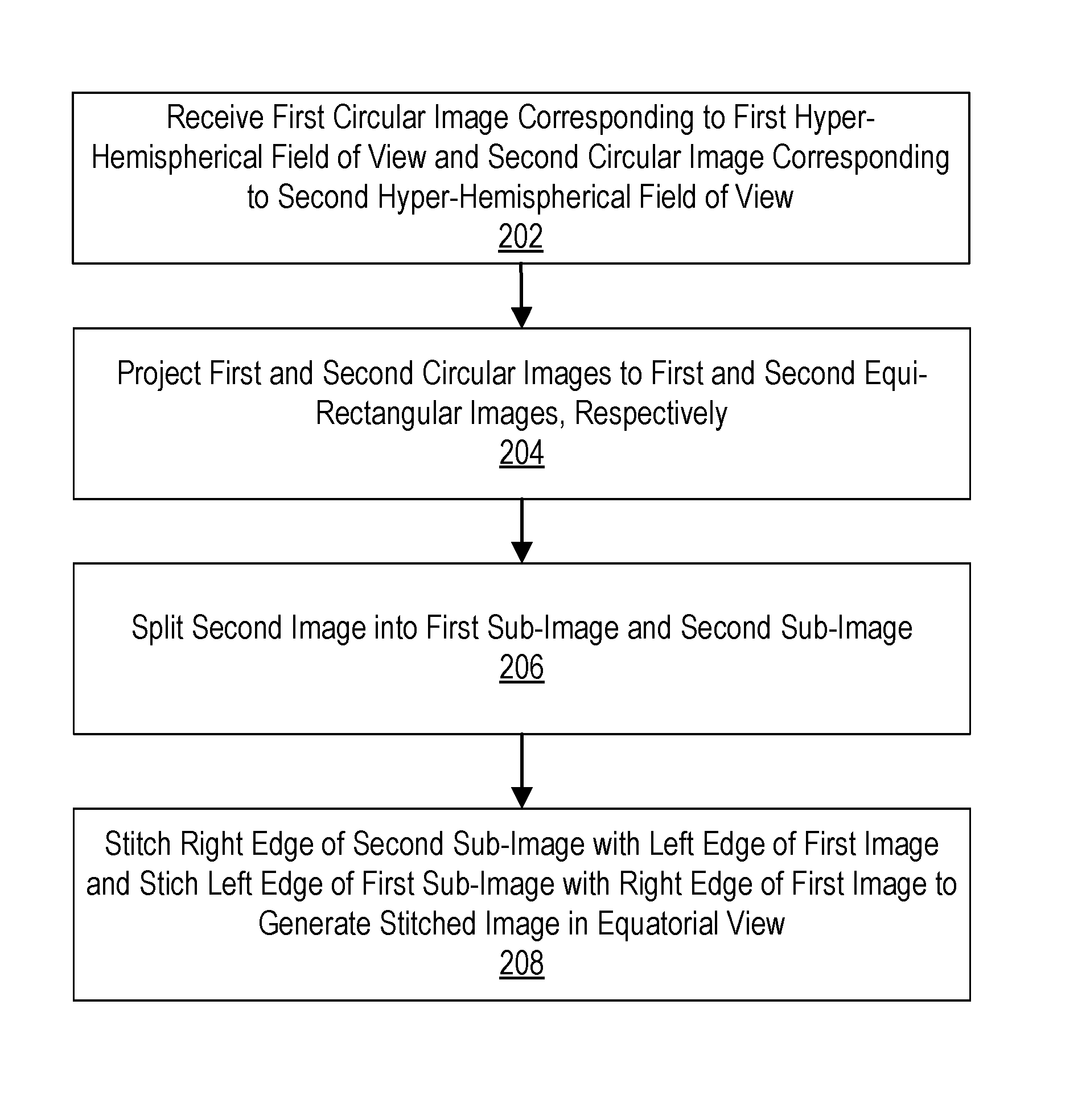
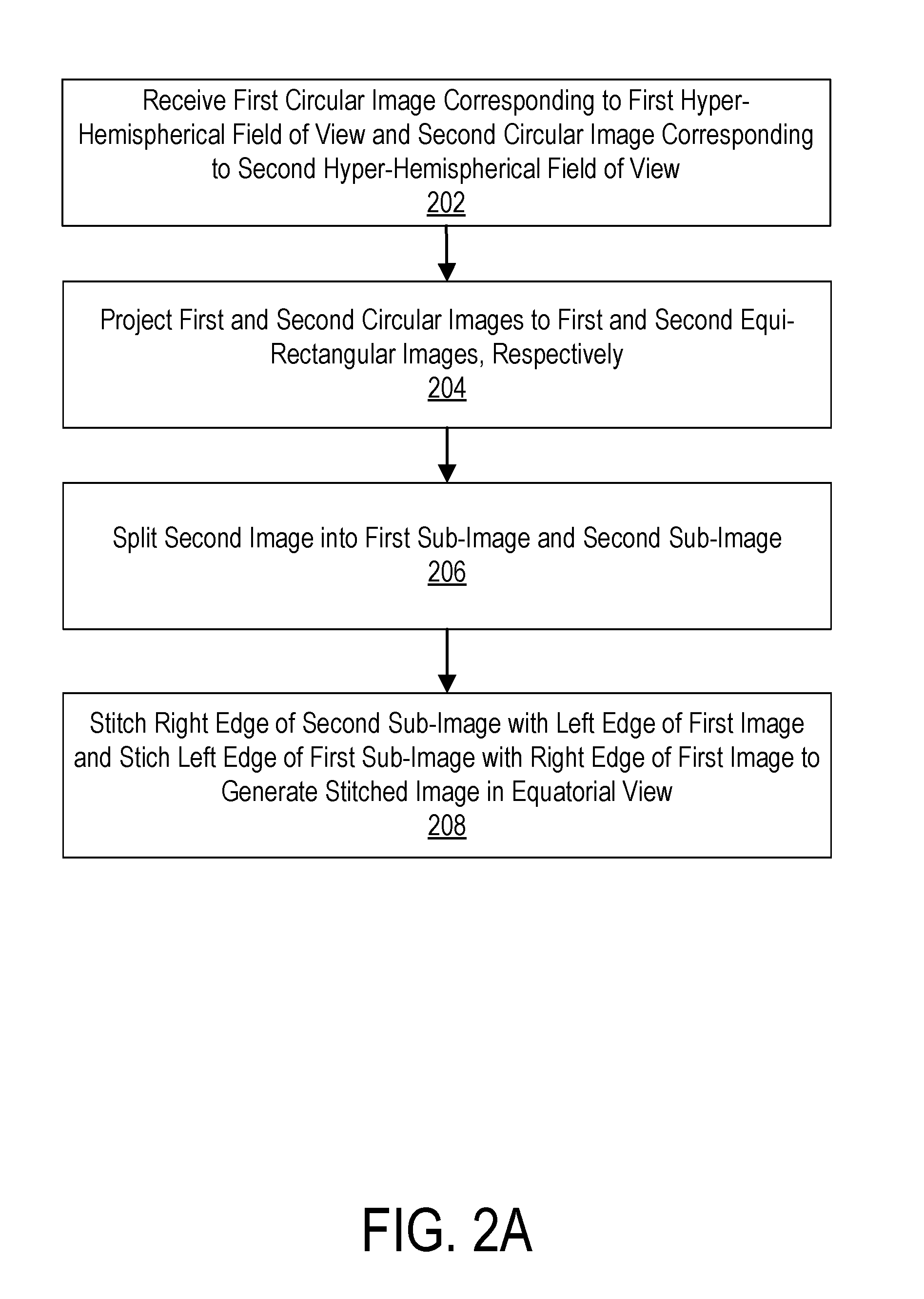
- Abstract
- Description
- Claims
- Application Information
AI Technical Summary
Benefits of technology
Problems solved by technology
Method used
Image

Examples
example camera
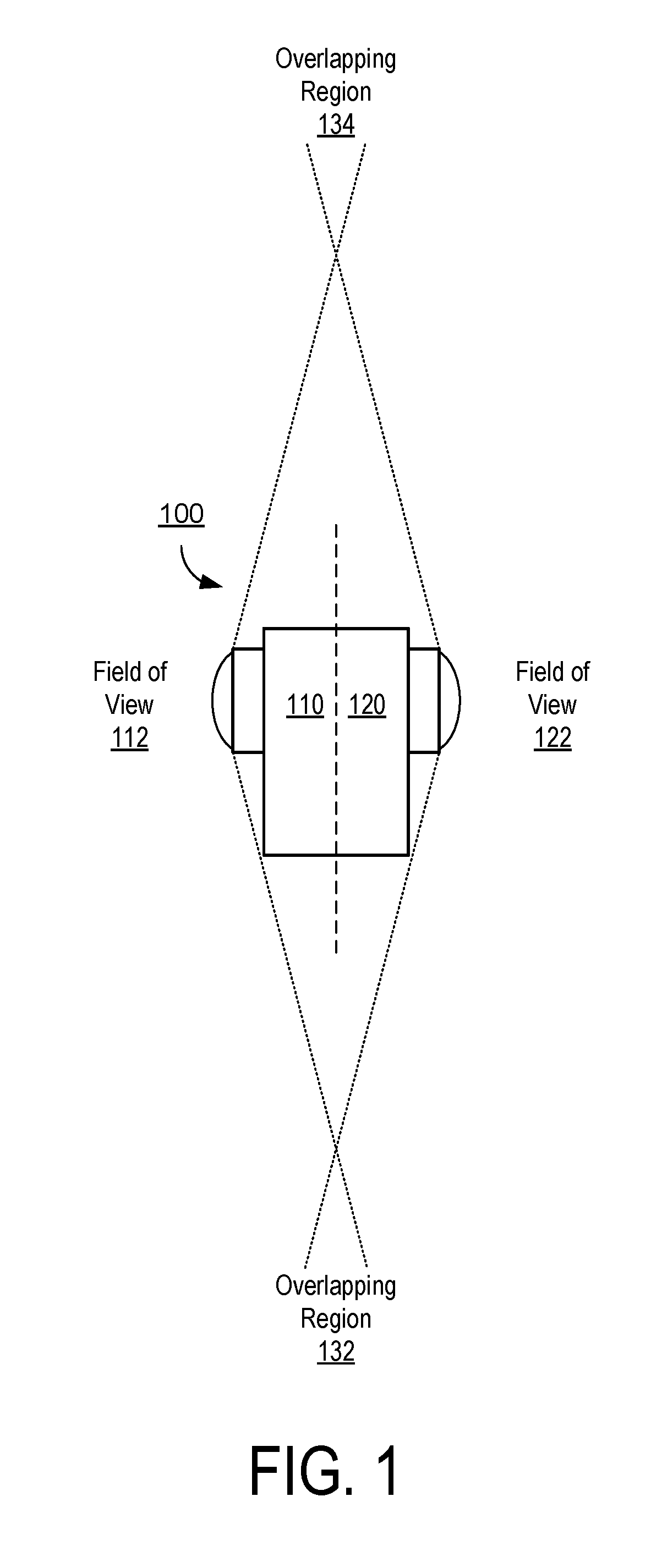
[0018]FIG. 1 illustrates an embodiment of an example spherical camera system 100 that may include a first camera 110 capturing a first field of view 112 and a second camera 120 capturing a second field of view 122. In an embodiment, the cameras 110, 120 may be integrated in a back-to-back configuration in which cameras 110, 120 face opposite directions. For example, in operation, the first camera 110 may be a “front-facing” camera 110 that a user may point towards an object or scene of interest and the second camera 120 comprises a “rear-facing” camera facing in an opposite direction of the front-facing camera 110. While the designations of front-facing and rear-facing are useful in describing the example processes herein, these designations are arbitrary and the camera system 100 may operate in any orientation. The fields of view 112, 122 may each comprise a hyper-hemispherical field of view that captures slightly greater than a 180° range in at least one direction. Because t...
example machine
Architecture
[0030]FIG. 5 is a block diagram illustrating components of an example computing system able to read instructions from a computer-readable medium and execute them in one or more processors (or controllers). The computing system in FIG. 5 may represent an implementation of, for example, the video processing device for performing the stitching processes described herein.
[0031]The computing system 500 can be used to execute instructions 524 (e.g., program code or software) for causing the computing system 500 to perform any one or more of the methodologies (or processes) described herein. In alternative embodiments, the computing system 500 operates as a standalone device or a connected (e.g., networked) device that connects to other computer systems. The computing system 500 may comprise, for example, a personal computer (PC), a tablet PC, a smart watch, or other device capable of executing instructions 524 (sequential or otherwise) that specify actions to be taken. In anot...
PUM
 Abstract
Description
Claims
Application Information