Linear power amplification method and linear power amplifier

a power amplifier and linear technology, applied in amplifier modifications, baseband system details, transmission monitoring, etc., can solve the problems of nonnegligible influence of signal amplification, delay in feedback route, and relationship between distortion components and values set in the lookup table that have not been clarified, and achieve excellent distortion compensation performan

Active Publication Date: 2007-01-30
NTT DOCOMO INC
View PDF27 Cites 35 Cited by
  • Summary
  • Abstract
  • Description
  • Claims
  • Application Information

AI Technical Summary

Benefits of technology

[0017]A primary object of the present invention is to provide a linear power amplification method and a linear power amplifi

Problems solved by technology

On the digital predistorter using the lookup table, however, the relationships between distortion components and values set in the lookup table have not been clarified nor has been presented any concrete method for correcting a slight variation in the nonlinear characteristic of the amplifier that is caused by a secular or temperature change, for instance.
However, widening of the frequency band for amplification provides increased frequency deviation in the gain and phase characteristics of the power amplifier as shown in FIG. 3, for instance,—this exerts nonnegligible influence on signal amplification.
In contrast to the analog predistorter, the lookup table type digital predistorter involves digitization of the pilot signal monitored from the amplifier output, giving rise to a problem of delay

Method used


Image

  • Linear power amplification method and linear power amplifier
  • Linear power amplification method and linear power amplifier
  • Linear power amplification method and linear power amplifier

Examples


first embodiment

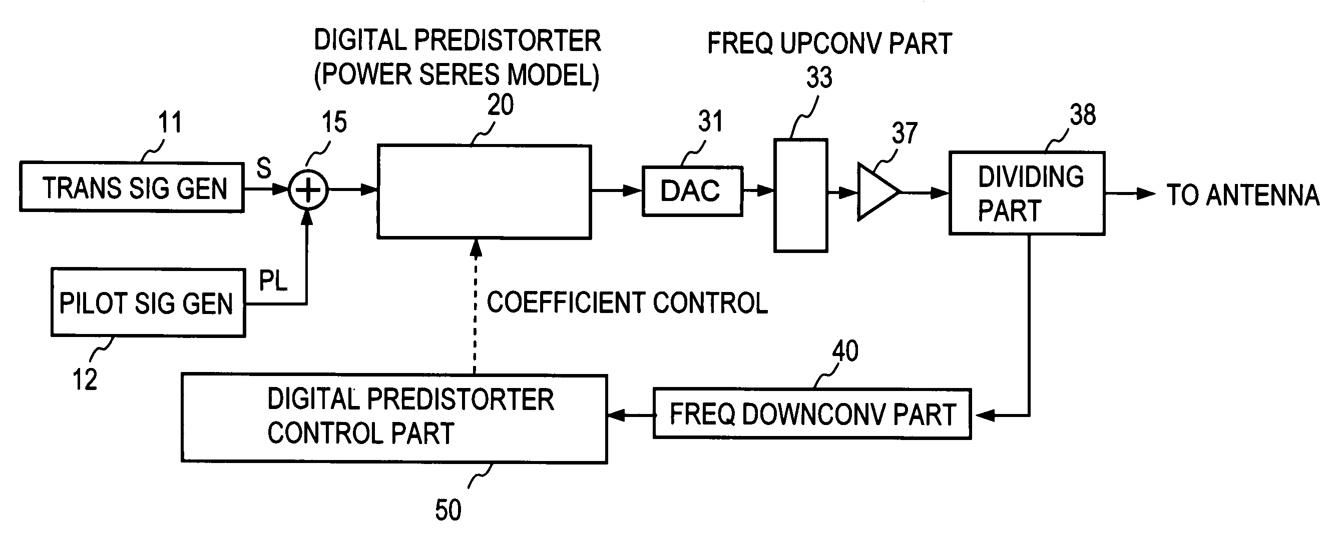
[0075]FIG. 5 illustrates a first embodiment of a linear power amplifier embodying the digital predistortion scheme according to the present invention. The pilot signal used in this embodiment is two tone signals PL1 and PL2 of the same level. The linear power amplifier of this embodiment comprises: a pilot signal generator 12 composed of tone signal generators 12A and 12B for generating the tone signals PL1 and PL2 through digital signal processing, and a digital adder 14; a digital predistorter 20; a DA converter 31; a frequency upconverting part 33 composed of a local oscillator 33A, a mixer 33B, and a band-pass filter 33C; a power amplifier 37; a directional coupler 38A and a pilot signal extracting band-pass filter 38B that constitute a dividing part 38; a frequency downconverting part 40 composed of a mixer 41, a band-pass filter 42, an amplifier 43, and an analog-to-digital (AD) converter 44; and a digital predistorter control part 50. The digital predistorter 20 is shown to h...

second embodiment

[0096]FIG. 8 illustrates in block form a second embodiment of the present invention, which is a modified form of the first embodiment. The illustrated embodiment employs one modulated wave signal as the pilot signal instead of using the two tone signals, and is identical in construction with the first embodiment except the configuration of the pilot signal generator 12. And this embodiment is also identical in operation with the first embodiment.

[0097]FIG. 9 shows, in the form of signal spectra, the injection and extraction of the pilot signal PL in the second embodiment. Rows A and B schematically show spectra of the input signal X to and the output signal Y from the digital predistorter 20, Rows C and D spectra of the input signal to and the output signal from the power amplifier 37, and Row E spectrum of the input signal to the control part 50. The spectra shown in FIG. 9 are identical with those in FIG. 6 except that the pilot signal PL in the second embodiment is a modulated si...

third embodiment

[0098]FIG. 10 illustrates in block form a third embodiment of the present invention, which differs from the first and second embodiments in that predistorters 201, 202 and DA converters 311 and 312 provided separately for the pilot signal and the transmission signal. The digital predistorters 201, 202 and the digital predistorter control part 50 therefor are identical in construction with those in the first and second embodiments.

[0099]In this embodiment there are newly provided a frequency upconverting part 34 composed of a local oscillator 34A, a mixer 34B and a band-pass filter 34C, for frequency converting the output from the second digital predistorter 202 to a band different from that of the transmission signal S. This embodiment contemplates widening the band of the transmission signal. The first and second embodiments permits reduction of computational complexities for predistortion, generation and injection of the pilot signals and digital signal processing, but widening th...


PUM


Abstract

A combined signal of a digital pilot signal and a digital transmission signal is applied to a digital predistorter (20), wherein it is added with odd-order distortions based on a power series model to generate a predistorted signal, then the predistorted signal is converted by a DA converter (31) to an analog signal, then the analog signal is upconverted by a frequency upconverting part (33) to a send frequency band, and the upconverted signal is output after being amplified by a power amplifier (37). A pilot signal component is extracted from the power amplifier output, then odd-order distortion components of the power series model are extracted by a digital predistorter control part (50) from the pilot signal component, and the odd-order distortions in the digital predistorter (20) are controlled to decrease the levels of the distortion components.

Description

BACKGROUND OF THE INVENTION[0001]The present invention relates to a linear power amplification method and a linear power amplifier for use in a radio communication transmitter, for instance.[0002]One of nonlinear distortion compensating schemes for microwave power amplifiers is a predistortion scheme using digital signal processing (hereinafter referred to as a digital distortion scheme) (for instance, H. Girard and K. Feher, “A new baseband linearizer for more efficient utilization of earth station amplifiers used for QPSK transmission,” IEEE J. on Selected Areas in Commun. VOL. SAC-1, NO. 1, January 1983). A feature of the digital predistortion scheme resides in obviating the necessity of using complex analog circuitry by implementing the operation of a predistorter through digital signal processing. Conventional linear amplifiers are formed primarily by analog circuits such as a feedforward amplifier and a negative feedback amplifier. The predistorter is also implemented in analo...

Claims


Application Information

Patent Timeline
IPC IPC(8): H03F1/30H03F3/66H03F1/32
CPCH03F1/3258H03F1/3247
Inventor SUZUKI, YASUNORIMIZUTA, SHINJIHIROTA, TETSUOYAMAO, YASUSHI
Owner NTT DOCOMO INC
Why Eureka
Try Eureka