Power supply having multi-vector error amplifier for power factor correction

a multi-vector error and amplifier technology, applied in the direction of electric variable regulation, process and machine control, instruments, etc., can solve the problems of large power loss, increased control bandwidth of multi-vector error amplifier, and increased power distribution system and transmission line stress, so as to reduce power output distortion, improve control bandwidth, and correct transient conditions quickly and smoothly

Active Publication Date: 2005-01-13
SEMICON COMPONENTS IND LLC
View PDF7 Cites 35 Cited by
  • Summary
  • Abstract
  • Description
  • Claims
  • Application Information

AI Technical Summary

Benefits of technology

[0019] It is a general objective of the present invention to provide a multi-vector error amplifier for the power factor correction circuit of a regulated power supply, that will reduce distortion in the power output during steady-state operation, while correcting transient conditions rapidly and smoothly. This is to be accomplished by automatically increasing the control bandwidth of the multi-vector error amplifier, and decreasing the gain, whenever a load change or other transient condition occurs.

Problems solved by technology

These high peak currents cause significant power losses due to heat dissipation.
Furthermore, they can put heavy stress on the power distribution system and the transmission lines.
These can occur whenever the output load changes, the power supply turns on or off, and when the supply input is affected by glitches or surges.
If the power supply does not react fast enough in these situations, the output voltage will also change, possibly beyond the predetermined operating range of the power supply.
This can result in an untimely shut down and possible circuit damage.
Unfortunately, achieving low signal distortion and fast response have traditionally been conflicting goals of regulated power supply design.
This is because a typical low bandwidth error amplifier filters out higher frequency signals from the feedback loop, meaning that it is a ‘slow’ component.
While this is necessary for eliminating current distortion, it reduces the responsiveness of the power factor correction circuit.
However, such compromises make it impossible to simultaneously achieve optimum performance in current distortion and transient response.
For the reasons described above, designing a power factor correction circuit that simultaneously provides low signal distortion and rapid transient response is fundamentally difficult.
Low current distortion requires a ‘slow’ error amplifier, but rapid transient response requires a ‘fast’ error amplifier.
The challenge is to design an error amplifier for a power factor correction circuit that filters out AC component ripple during steady-state operation, while quickly and smoothly responding to sudden changes in the output load and the supply voltage.
One drawback of the Kammiller invention is that it fails to decouple steady-state operation from transient-mode operation.
This design can increase the overall speed of the feedback loop, but only to a limited degree.
Transient-mode feedback control signals are still severely bandwidth-limited by what is effectively a low-pass filter.
The transient response of the circuit is still subject to limitations imposed by the requirements of steady-state operation.
Another drawback of the Kammiller invention is that it is prone to instability.
It is well known to those skilled in the art that simultaneously increasing power gain and bandwidth tends to cause a feedback control system to become unstable.
Furthermore, the said resistor switching mechanism will result in very abrupt and sudden transitions, further putting stress on the circuit and endangering stability. FIG. 3A illustrates the transient response of the Kammiller design.
Another drawback of the Kammiller invention is that the transient response is slow.
The low bandwidth amplifier introduces a phase delay into the power factor correction control signal.
Despite the resistance switching mechanism, transient feedback signals must still pass through this component and suffer a phase delay.
Another drawback of the Kammiller invention is high production cost.
As explained above, the transient response of the Kammiller design is susceptible to instability.
The increased cost of this is very high relative to the overall cost of the circuit.
Without knowing how to build the invention, it is difficult to assess.
Any practical implementation of the variable resistance mechanism will be cumbersome and expensive relative to the overall cost of the circuit.
Furthermore, the switching mechanism may introduce other complications that would need to be addressed.

Method used


Image

  • Power supply having multi-vector error amplifier for power factor correction
  • Power supply having multi-vector error amplifier for power factor correction
  • Power supply having multi-vector error amplifier for power factor correction

Examples


Embodiment Construction

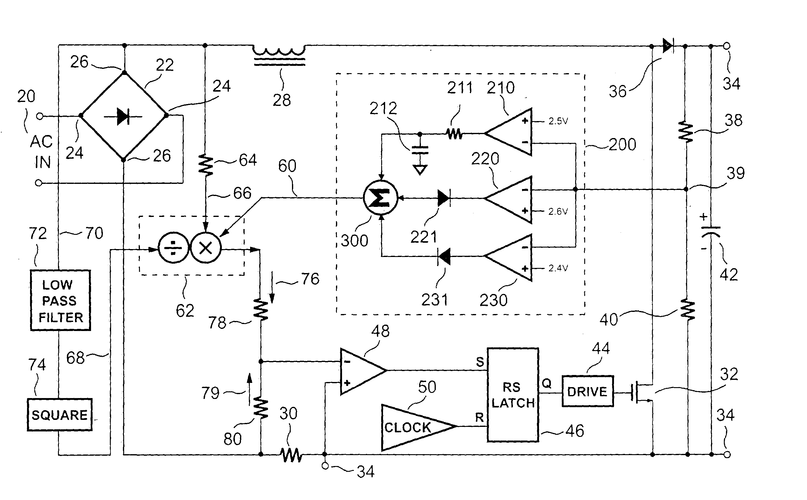
[0036] Referring now to the drawings wherein the contents are for purposes of illustrating the preferred embodiment of the invention only and not for purposes of limiting same, FIG. 4 shows a block diagram of a known regulated power supply with power factor correction.

[0037] In this circuit, a bridge rectifier 22 receives an AC input signal 20 at an AC input 24. An output 26 of the bridge rectifier 22 is connected to an inductor 28 and a current-sense resistor 30. The inductor 28 and the current-sense resistor 30 are connected together to form a loop, through a switch 32. The switch 32 may be any of several components, including a FET switch or some other type of known switching device.

[0038] When the control circuitry closes the switch 32, the voltage from the bridge rectifier 22 is applied to the inductor 28. The current passing through the inductor 28 starts to increase. Eventually, the switch 32 opens and the current flowing through the inductor 28 flows through a diode 36 to ...


PUM


Abstract

A regulated power supply having power factor correction control includes a multi-vector error amplifier. The multi-vector error amplifier provides an error signal that is used to regulate a switching mechanism of the power supply. The multi-vector error amplifier acts to provide a low distortion error signal during steady-state operation, while responding rapidly and smoothly to sudden load changes.

Description

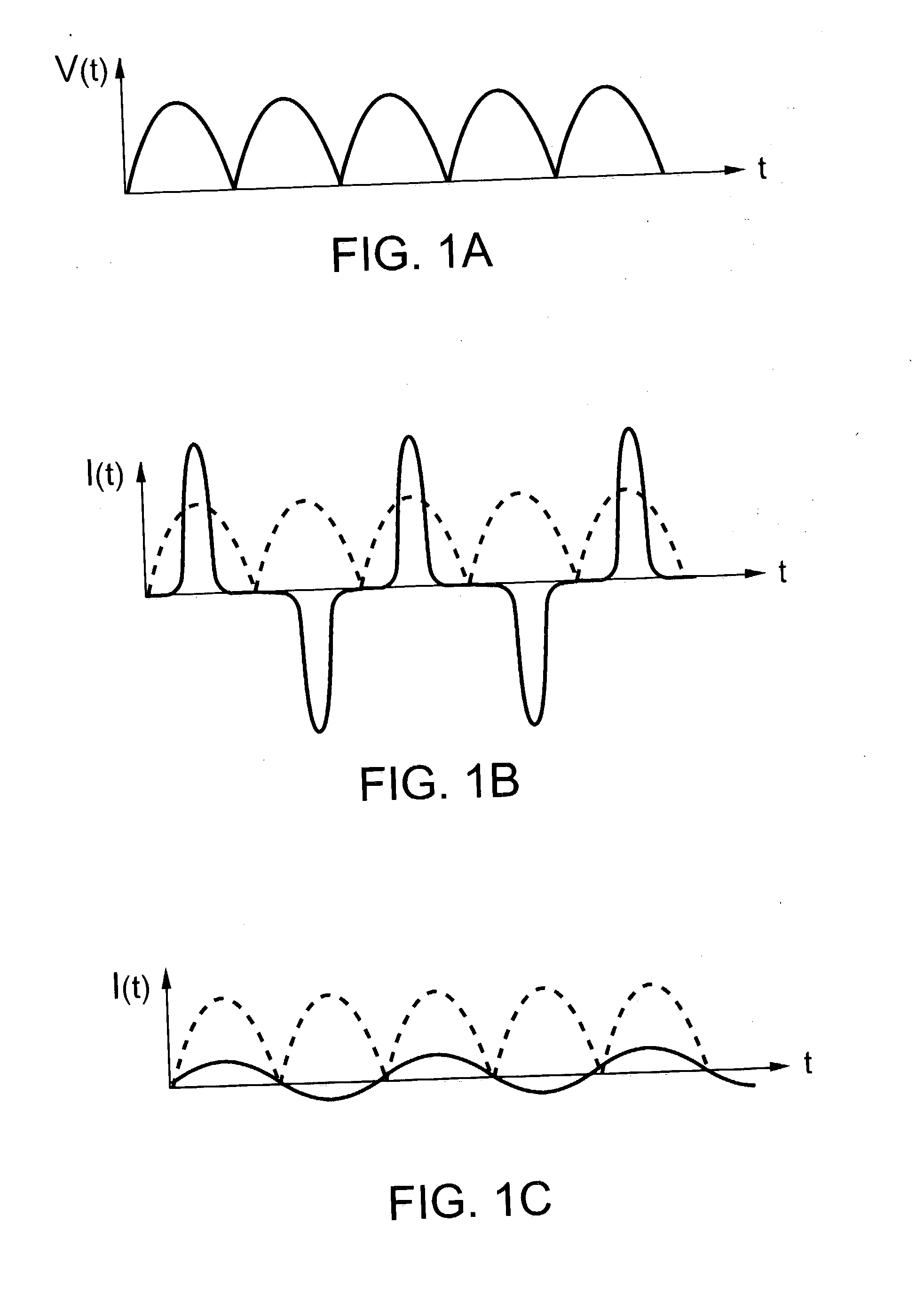
BACKGROUND OF THE INVENTION [0001] 1. Field of the Invention [0002] The present invention generally relates to the art of power supplies and more particularly, to a regulated power supply with power factor correction (PFC) control. [0003] 2. Description of the Related Art [0004] Regulated power supplies are used for power conversion in many applications, including computers, lighting ballasts, and telecommunications devices. Products consuming 70 watts or more generally require regulated power supplies with power factor correction, to reduce power loss and comply with environmental regulations. In these and other products where significant load variations are frequent, regulated power supplies capable of reacting rapidly to sudden load changes are especially desirable. [0005] Without power factor correction, an AC / DC power conversion system will draw current through the rectifier in sharp bursts, shown in FIG. 1B. These high peak currents cause significant power losses due to heat d...

Claims


Application Information

Patent Timeline
Patent Type & Authority Applications(United States)
IPC IPC(8): G05F1/40G05F1/56H02M1/00H02M1/42H02M7/00
CPCH02M1/4225Y02B70/126H02M2001/4275Y02B70/10H02M1/4275
Inventor YANG, TA-YUNGLEU, YI-HSINCHEN, CHERN-LINLIN, JENN-YU G.
Owner SEMICON COMPONENTS IND LLC
Why Eureka
Try Eureka