
Plug device and method of automatically plugging display panel with connector

a technology of display panel and plug device, which is applied in the direction of static indicating device, coupling device connection, instruments, etc., can solve the problems of large labor intensity of testers, low plug speed and accuracy, and errors in plugging, so as to reduce the number of testers on the assembly line, improve plug speed and accuracy, and reduce labor intensity

Inactive Publication Date: 2017-02-16
BOE TECH GRP CO LTD +1
View PDF6 Cites 0 Cited by
  • Summary
  • Abstract
  • Description
  • Claims
  • Application Information

AI Technical Summary

Benefits of technology

The present invention aims to provide a plug device and method for automatically plugging a display panel with a connector, which has the advantage of reducing the number of testers on the assembly line, their labor intensity, and improving plug speed and accuracy. The plug device may also prevent damage to the connection and improve applicability of the device. Additionally, it aims to improve accuracy of automatic plug between the connector and display panel, and prevent damage to the plug interface of the display panel.

Problems solved by technology

Firstly, the connection between the display panel and the connector is realized by being manually plugged by testers, thus a great number of testers are desired along the assembly line of display panels. Meanwhile, testers bear great labour intensity during operation.
Secondly, during the process of plugging the display panel with the connector, plug speed and accuracy are relatively low due to limitations in testers experience, unavoidable plugging errors during the process of manual plug and the like.

Method used


Image

  • Plug device and method of automatically plugging display panel with connector
  • Plug device and method of automatically plugging display panel with connector

Examples


Embodiment Construction

[0062]Hereinafter, specific embodiments of the disclosure will be described in detail in conjunction with the accompanying drawings. It should be understood that the specific embodiments as set forth herein are merely for the purpose of illustration and explanation of the disclosure and should not be constructed as a limitation thereof.

[0063]According one aspect of the invention, there is provided a plug device, especially a plug device for automatically plugging a display panel with a connector.

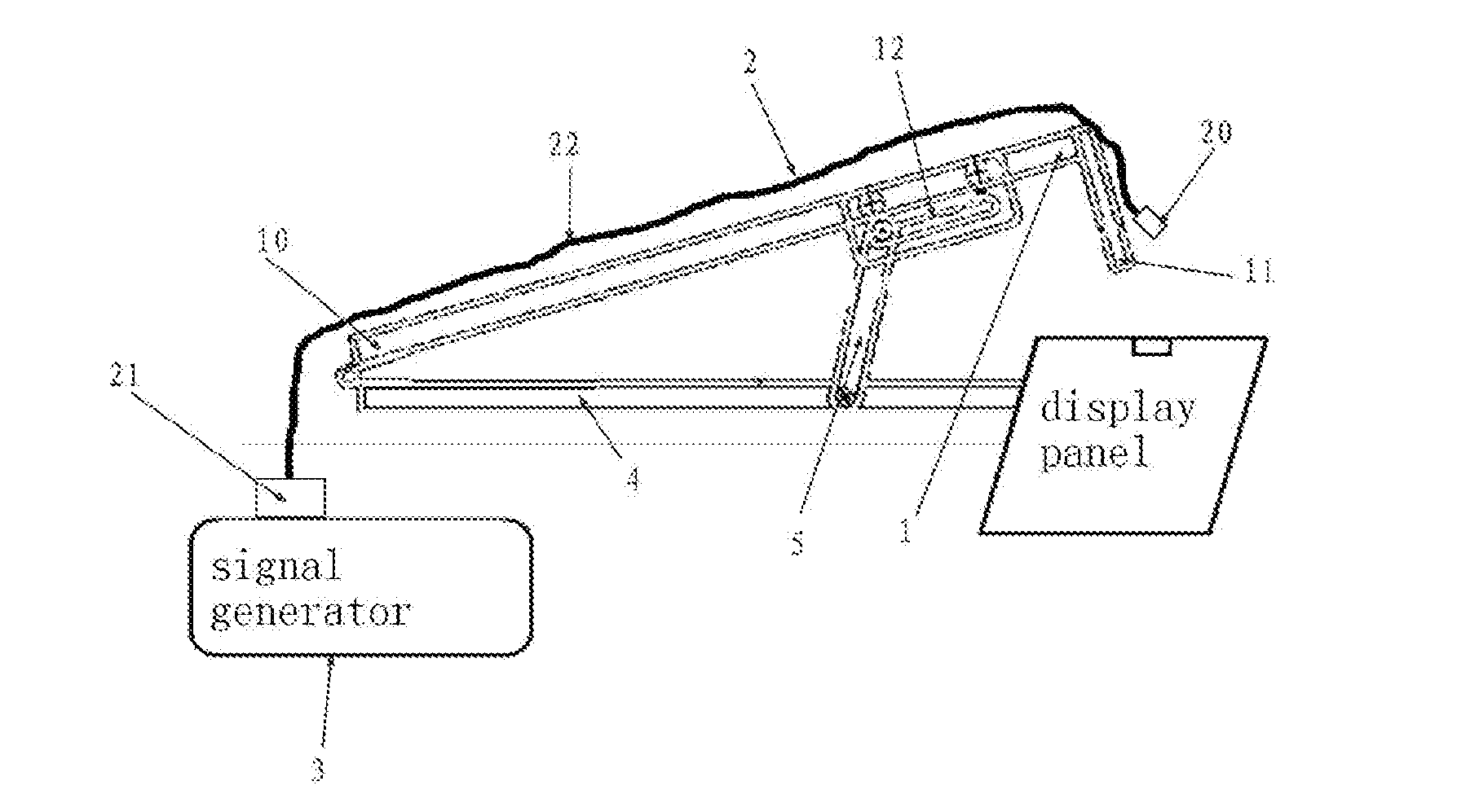
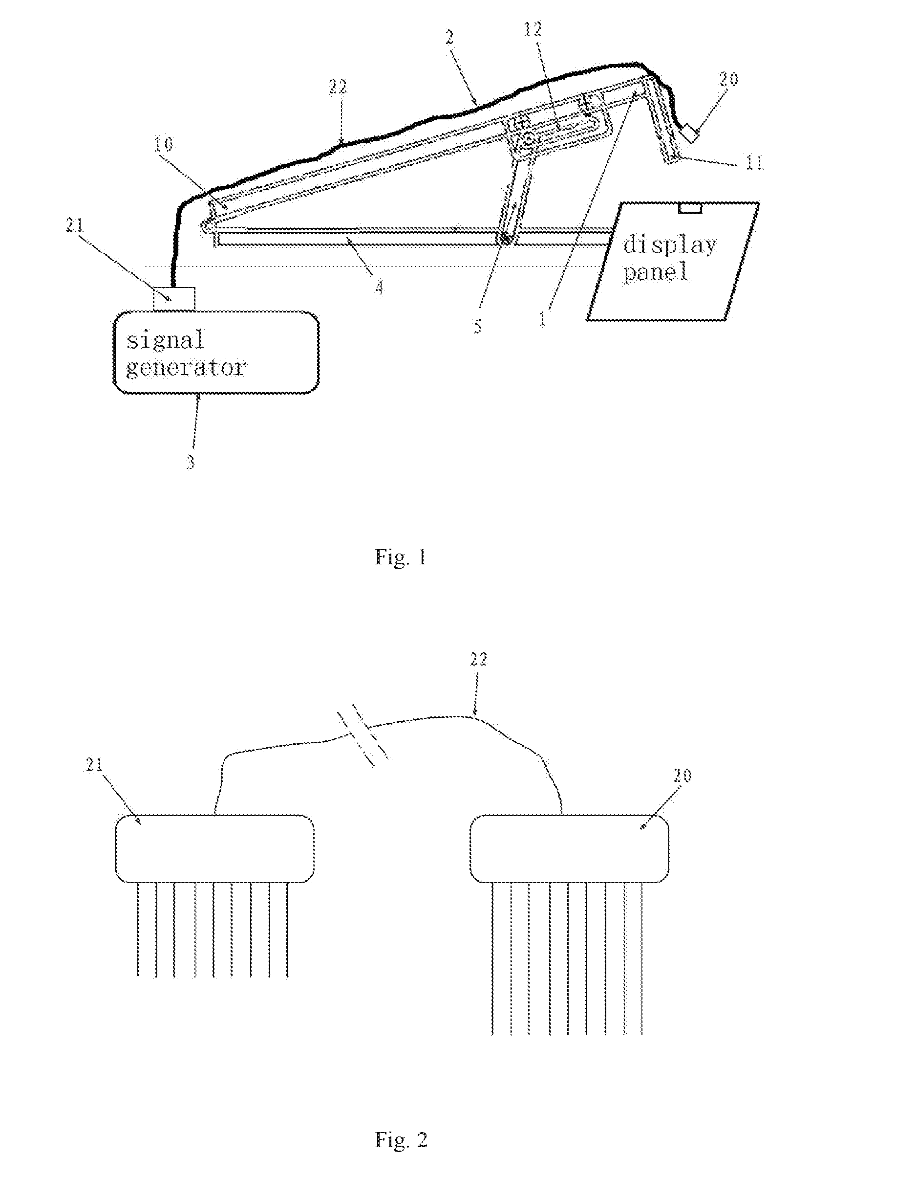
[0064]FIG. 1 is a schematic view showing a plug device according to the exemplary embodiment of the invention. As shown in FIG. 1, in this embodiment, the plug device comprises a first linkage 1 having a fixed end 10 and a movable end 11 that can approach or get away from the display panel at a plug location, wherein a connector 2 comprises a first connector head 20, a second connector head 21 and a wire 22 that connects the first and second connector heads, the connector 2 is mounted on the...


PUM


Abstract

The present invention relates to a plug device and a method of automatically plugging a display panel with a connector. The plug device for automatically plugging a display panel and a connector comprises a first linkage having, a fixed end and a movable end that can approach or get away from the display panel at a plug location; wherein the connector comprises a first connector head, a second connector head and a wire that connects the first and second connector heads, the connector is mounted on the first linkage, the first and second connector heads of the connector are respectively secured on the movable end and the fixed end of the first linkage; and wherein the second connector head is connected with a signal generator, when the movable end approaches the display panel at the plug location, the first connector head is automatically plugged on the display panel.

Description

FIELD OF THE INVENTION[0001]The present invention relates to a plug device, and particularly relates to a plug device that automatically plugs a connector with a display panel during Aging Test, and a method of automatically plugging a display panel with a connector.BACKGROUND OF THE INVENTION[0002]In the preparation techniques of display panels, the prepared display panel needs to go through Aging Test to test its life span and reliability. Aging Test is a kind of lighting test which refers to tests conducted at a state where the display panel is displaying. It is to be understood that during Aging Test, an external light source is needed to provide light rays for the display panel, while a drive signal is also needed to be provided for the display panel to display.[0003]In the prior art, the signal generator is connected with the display panel via a connector, so as to provide drive signals for the display panel. Specifically, the connector comprises a first connector head, a seco...

Claims


Application Information

Patent Timeline
Patent Type & Authority Applications(United States)
IPC IPC(8): H01R13/629
CPCH01R13/629G01R31/282G09G3/006H01R13/62933H01R43/26H01R2201/20
Inventor PAN, DENGLI, FANGQINGDAI, WEIWANG, WEIWEIFU, WENHUA
Owner BOE TECH GRP CO LTD
Learn More