Method for moving an elevator car

Active Publication Date: 2017-02-23
KONE CORP
View PDF19 Cites 7 Cited by
  • Summary
  • Abstract
  • Description
  • Claims
  • Application Information

AI Technical Summary

Benefits of technology

[0004]It is therefore object of the present invention to facilitate the releas

Problems solved by technology

Therefore the overspeed governor cannot be used in connection with the car approach to the end areas of the elevato

Method used


Image

  • Method for moving an elevator car
  • Method for moving an elevator car

Examples


Example

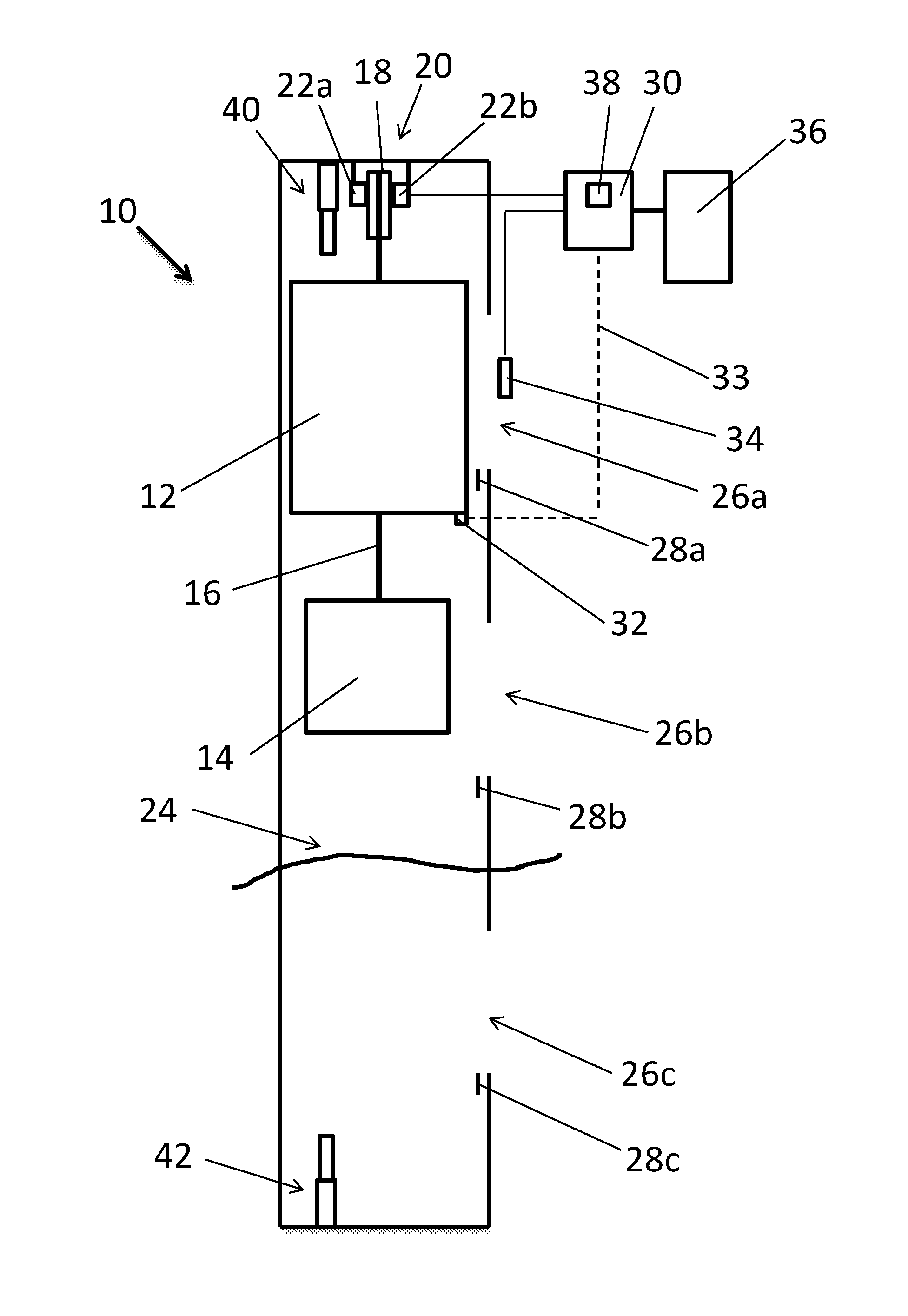
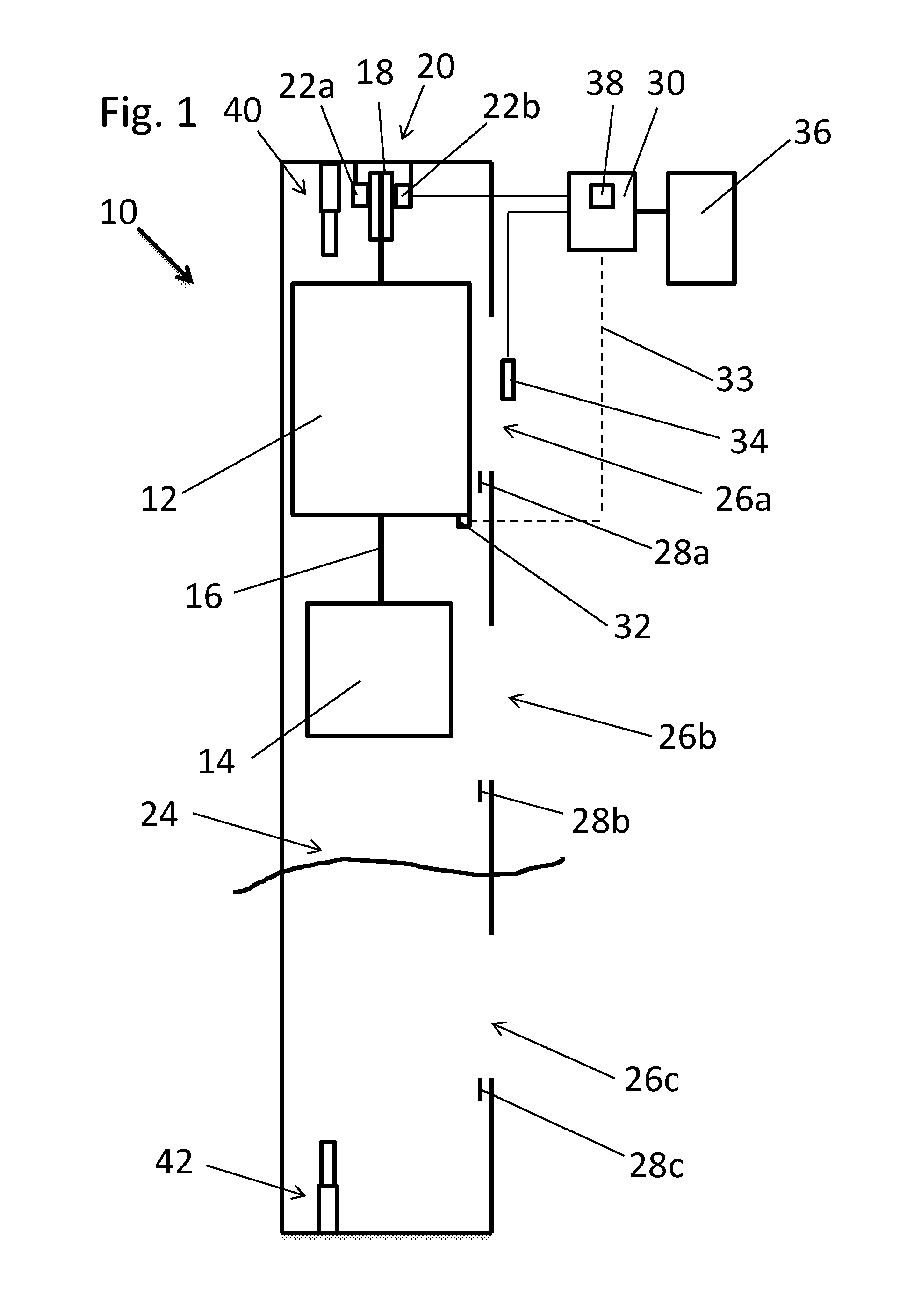
[0031]The inventive elevator 10 comprises an elevator car 12 and a counterweight 14 suspended on hoisting ropes 16 running over a traction sheave 18 of a drive unit 20. The drive unit 20 comprises two electric elevator brakes 22a,b which grip advertent brake surfaces of the traction sheave.

[0032]The elevator car 12 as well as the counterweight 14 are running vertically in an elevator shaft 24 which has several landings 26a-c. The FIGURE shows the highest landing 26a as well as the lowest landing 26c. In the top of the elevator shaft 24 an upper end buffer 40 is located. The end buffer can also be a buffer arrangement comprising car and counterweight buffers. In the shaft pit a lower end buffer 42 is located.

[0033]In the elevator shaft, preferably at the bottom of each landing 26a-26c, a door zone indicator 28a-c is located. The uppermost door zone indicator 26a is an upper end limit indicator whereas the lowest door zone indicator 26c is a lower end limit indicator. The elevator 10 ...


PUM


Abstract

A method is provided for moving an elevator car in a rescue operation after at least one electric elevator brake have been actuated, whereafter the brake is re-opened via a manual brake opening device and operated to allow a movement of the elevator car to a next landing. The manual brake opening device is connected to an end limit indicator detector, which end limit indicator detector is configured to issue an end limit signal when elevator car arrives at an area of an end limit indicator at the end of its movement range of the elevator car in the elevator shaft. When the end limit indicator detector outputs an end limit signal to the manual brake opening device, the elevator brake is actuated by the manual brake opening device to stop the elevator car.

Description

BACKGROUND OF THE INVENTION[0001]The present invention relates to a method for moving an elevator car in an emergency ride after at least one electric elevator brake has been actuated by a safety device of an elevator.DESCRIPTION OF THE RELATED ART[0002]Elevators usually have a variety of safety functions for stopping the elevator car depending on the status of different elevator components. For example one safety contact is provided in connection with each landing door whereas other safety contacts are located in connection with the elevator drive and other components of the elevator. If one of these electric contacts opens the elevator drive stops and the electric elevator brake, usually two electric elevator brakes, are activated (deenergized) as to grip a rotating part of the drive, for example the traction sheave, to stop the elevator car. Also in case of power-off the car may stop somewhere in the shaft. In these situations the car normally doesn't stop in the entrance / exit ar...

Claims


Application Information

Patent Timeline
IPC IPC(8): B66B5/02
CPCB66B5/027
Inventor VIITA-AHO, TARVOLAHTEENMAKI, JUSSI
Owner KONE CORP
Why Eureka
Try Eureka