Profile connector and profile assembly

a technology of profile connectors and assembly parts, applied in the direction of rod connections, fastening means, mechanical instruments, etc., can solve the problems of not being able to tighten the anchor bolt, being a large number of separate parts, and remaining possible for the profile bars, etc., to achieve a relatively easy assembly and simple design

Active Publication Date: 2017-02-23
FLAIG HARTMUT
View PDF0 Cites 5 Cited by
  • Summary
  • Abstract
  • Description
  • Claims
  • Application Information

AI Technical Summary

Benefits of technology

[0011]As will be explained later with regard to the profile assembly according to the invention, the forming geometry makes it possible for the first time to preassemble the profile connector for producing a profile assembly in a defined way, for which purpose the profile connector, particularly the body thereof, is dimensioned such that the anchor bolt can be tightened until the body of the profile connector with its forming geometry lies flush against the face side of the first profile bar, i.e., is braced there (still without having been formed into the face side of the first profile bar), and in this state the gap or distance between the at least one bracing leg and the face side of the first profile connector is larger, in particular larger by a clearance dimension, than the thickness or height extension of the at least one undercut of the undercut elongated groove of the second profile bar measured in the same direction, thus making it possible in this respect, when the profile connector is in the preassembled state with the anchor bolt tightened, for the second profile bar to be pushed onto the preassembled profile connector, more precisely onto the body thereof, so that the second profile bar can then be shifted farther towards the first face side of the first profile bar by tightening the at least one clamping screw at the desired shifted position (with the forming geometry into the material of the first profile bar), in order to fix the profile bars to one another (permanently and in torsion-proof manner) and at the same time shape the forming geometry of the body of the first profile connector into the material of the first profile bar. Expressed another way, it is provided in a refinement of the invention that an overall height extension of the body aligned parallel to the lengthwise extension of the anchor bolt is chosen with the forming geometry such that when the body of the profile connector is seated in the undercut elongated groove of the second profile bar the second profile bar is displaceable relative to the body and to the first profile bar along the lengthwise extension of the undercut elongated groove of the second profile bar. In the preassembled state, the body of the first profile bar is reliably prevented from twisting by the frictionally engaged contact on the face side of the first profile bar.
[0035]According to a particularly preferred embodiment, as was described in the introduction, the profile connector has a countersunk section for frontal countersinking in an undercut elongated groove of the first profile bar. Most particularly preferably, two countersunk sections are provided at a distance from each other along the longitudinal extension of the profile connector. The at least one countersunk section in a completed profile assembly is preferably accommodated in an undercut elongated groove of the first profile bar, thereby ensuring additional torsion-proofing.

Problems solved by technology

This problem is also the reason why there is no defined bearing or bracing area for the first clamping screw on the anchor bolt.
It is also disadvantageous that, despite the non-positive connection between the first and second profile bars, it is still or remains possible for the profile bars to twist about the longitudinal centre line of the anchor bolt.
This disadvantage of the known profile connector is the fact that it consists of many separate parts.
Moreover, a problem this known profile connector is that the anchor bolt cannot be tightened until it is immovable, to enable the second profile bar to be pushed on.
In this case too, a defined preassembly is not possible.
Defined preassembly is not possible.
A defined pre-assembly of the profile connector frontally on a profile bar is not possible.

Method used


Image

  • Profile connector and profile assembly
  • Profile connector and profile assembly
  • Profile connector and profile assembly

Examples


Embodiment Construction

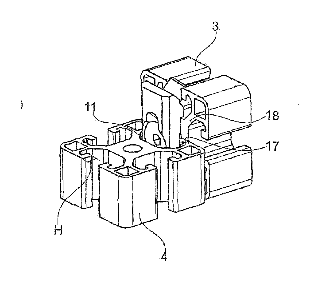
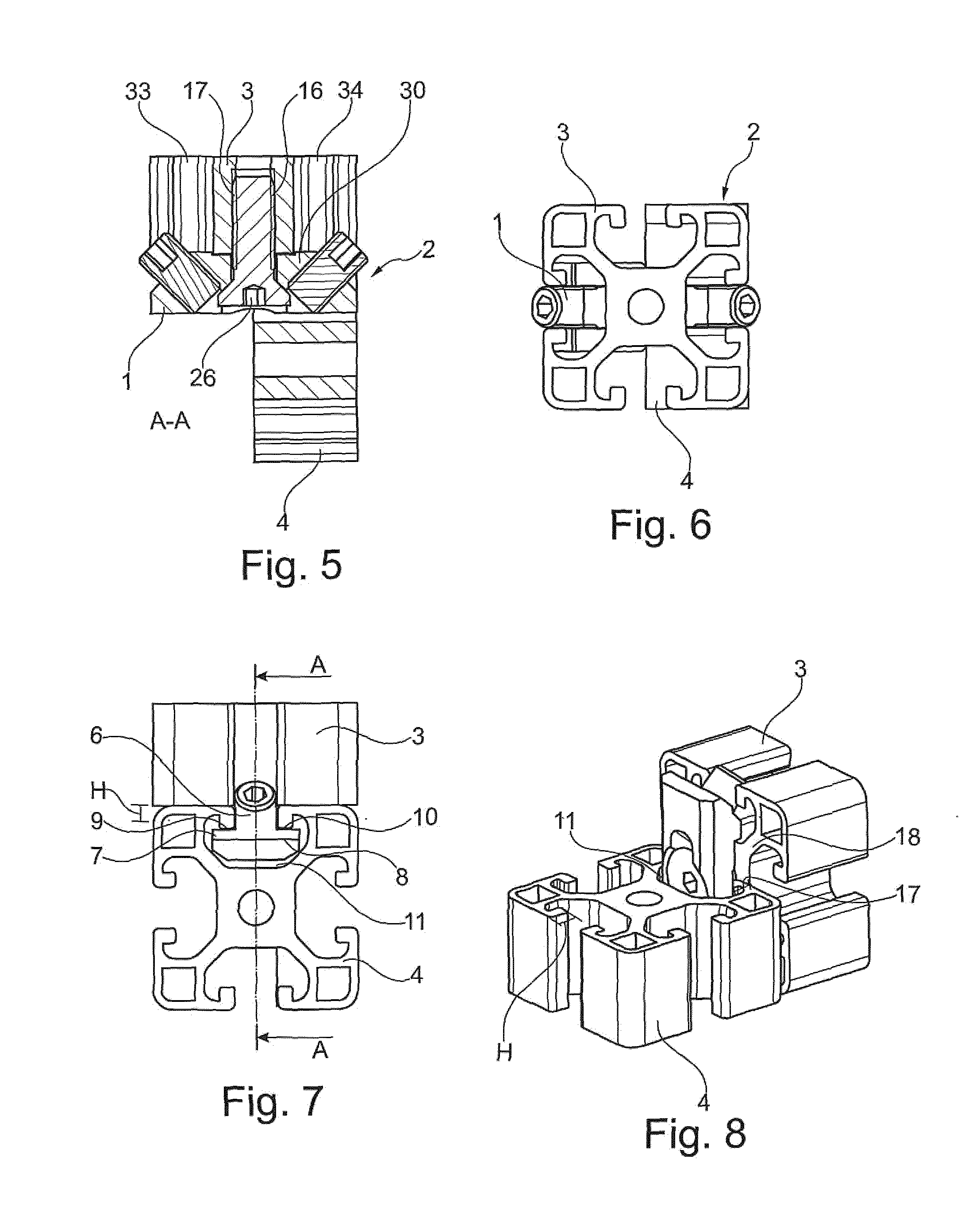
[0055]As is made evident by FIGS. 5 to 8, the profile connector of FIGS. 1 to 4 is used to produce a profile assembly 2 which besides profile connector 1 also comprises a first profile rod 3 and a second profile rod 4 aligned orthogonally thereto.

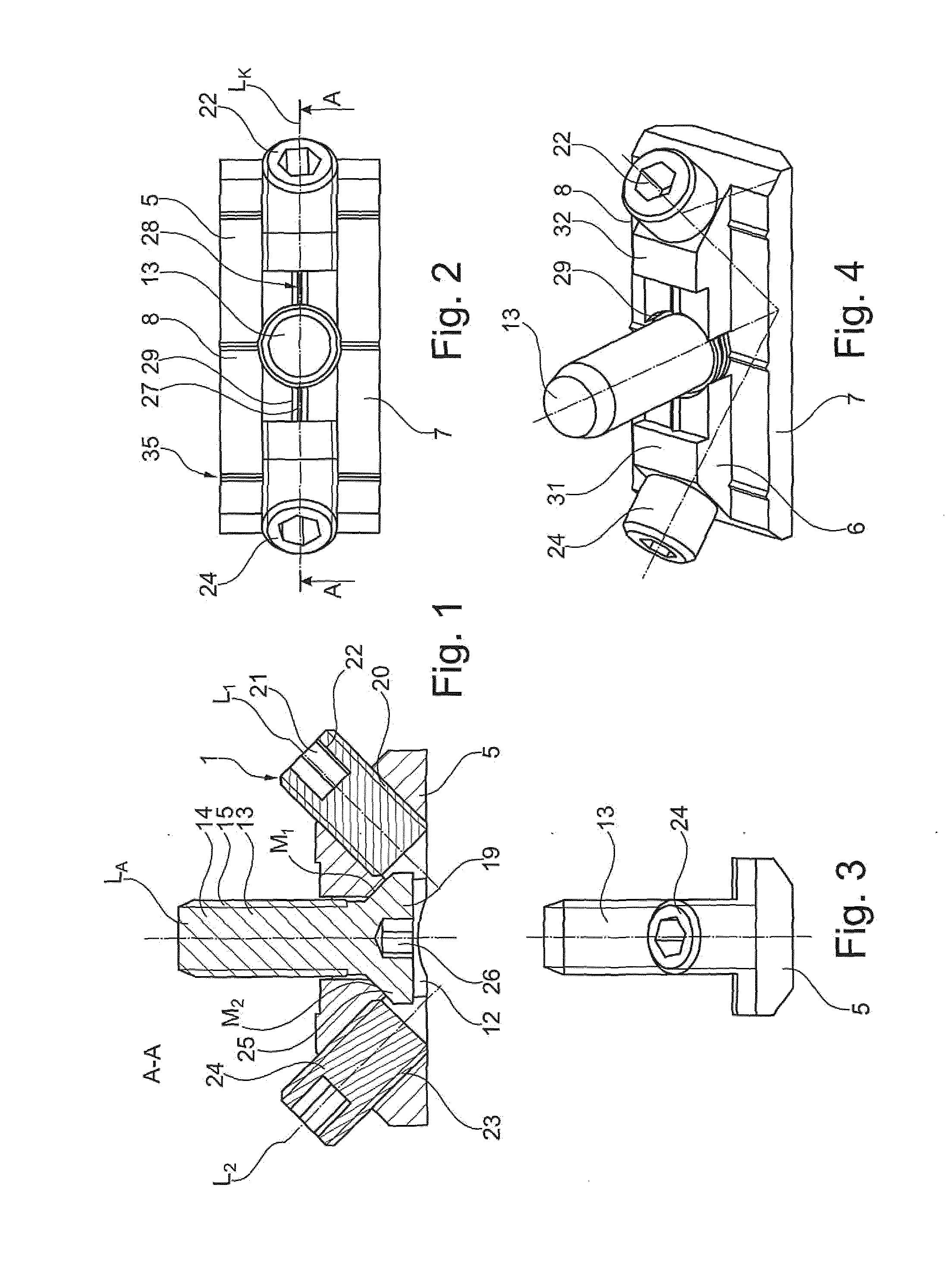
[0056]From FIGS. 1 to 4, it may be seen that profile connector 1 comprises a body 5 as a cold extruded part made from steel, which in the cross sectional view of FIG. 3 is in the shape of a “T”. Body 5 is equipped with an elevated comb bar 6 (in the direction of the first profile bar), which surpasses the two lateral bracing legs 7, 8, each of which is braced against the underside of an undercut 9, 10 of an undercut elongated groove 11 in second profile bar 4 in a profile assembly, in this way tightening second profile bar 4 towards first profile bar 3 and applying a tensile force thereto.

[0057]A through opening 12 is provided in body 5, or more precisely in the comb bar 6 that extends beyond bracing legs 7, 8, in this case preferably in th...


PUM


Abstract

Profile connector for connecting a first and a second profile bar (3, 4), made from a light metal alloy, with a body (5) which can be accommodated in an undercut elongated groove (34) in the second profile bar (4) and has at least one bracing leg (7) for bracing against an undercut (9, 10) of the undercut elongated groove (34) of the second profile bar (4), and an anchor bolt (13) which is accommodated in a through opening (12) that is created in the body (5) and extends at right angles to a longitudinal extension of the body (5), which anchor bolt has an anchor bolt head and fixes the profile connector (1) frontally, on the first profile bar (3), and with a first clamping screw (22) accommodated in an internal threaded opening (20) provided inside the body (5) and extending at an angle to a longitudinal centre line (LA) of the through opening (12), which clamping screw serves to displace the body (5) along the anchor bolt (13) away from the anchor bolt head (19) towards the first profile bar (3) by tightening the first clamping screw (22) in the internal thread of the first internal threaded opening (20), thereby bracing the first clamping screw (22) on the anchor bolt (13), wherein a forming geometry (29) is conformed and arranged on the body (5) for shaping frontally into the first profile bar (3) by tightening the first clamping screw (22) to create a positive locking connection between the body (5) and the first profile bar (3).

Description

BACKGROUND OF THE INVENTION[0001]The invention relates to a profile connector for connecting two profile bars, each of which is made in particular from a light metal alloy, and each most particularly preferably having at least one undercut elongated groove. The profile bars themselves are not part of the profile connector, but they can be attached to each other at right angles to one another with the connector. The profile connector comprises a body preferably in the form of a cold extruded part, most particularly preferably made of steel, with a side preferably consisting of a comb bar and which when fitted faces towards the first profile bar, preferably a bearing side for bearing on a first profile bar, particularly on a face side of a first profile bar, wherein the body may be accommodated in an undercut elongated groove, particularly a T-groove, of a second profile bar. The body has at least one bracing leg for bracing against an undercut in the undercut elongated groove of the ...

Claims


Application Information

Patent Timeline
Patent Type & Authority Applications(United States)
IPC IPC(8): F16B7/18
CPCF16B7/187F16B7/0453F16B7/0466
Inventor FLAIG, HARTMUT
Owner FLAIG HARTMUT
Why Eureka
Try Eureka