
Connector assembly for mounting lighting fixture

a technology for connecting assemblies and lighting fixtures, which is applied in the direction of lighting support devices, lighting and heating apparatus, and lighting protection devices, etc. it can solve the problems of difficult handling of lighting fixtures, dangerous and cumbersome installation processes, and the conventional process of assembling and installing lighting fixtures can be difficult, so as to facilitate the installation of lighting fixtures and reduce associated installation and/or maintenance times.

Inactive Publication Date: 2017-02-23
GE LIGHTING SOLUTIONS LLC
View PDF0 Cites 10 Cited by
  • Summary
  • Abstract
  • Description
  • Claims
  • Application Information

AI Technical Summary

Benefits of technology

The patent describes a need for assemblies and methods that make it easier to install lighting fixtures on planes that don't run parallel to each other. It also aims to reduce installation and maintenance times. Additionally, the patent states that the lighting fixtures can be easily removed and reinstall without removing adjacent fixtures, which can save time during maintenance.

Problems solved by technology

These characteristics can make lighting fixtures difficult to handle.
Particularly, the conventional process of assembling and installing lighting fixtures can be challenging, and require installers to engage in complex, dangerous and cumbersome installation processes.
Such processes are not only time-consuming, but can be costly to consumers.
For elongated lighting fixtures with lengths from about 4-8 feet, for example, the act of mounting the fixtures at heights about 10 feet in the air is cumbersome.
This mounting typically requires at least two installers and a significant time commitment to complete the assembly process.
Although this alternative method can be completed with a single person, current lighting fixtures are not designed to accommodate this configuration.
An additional problem with the conventional installation techniques is the requirement to be mounted on a parallel or co-linear planes (e.g., abutting the lighting fixtures end-to-end).
Without these co-linear planes, the fasteners cannot properly attach the lighting fixtures together.

Method used


Image

  • Connector assembly for mounting lighting fixture
  • Connector assembly for mounting lighting fixture
  • Connector assembly for mounting lighting fixture

Examples


Embodiment Construction

[0021]While the present invention is described herein with illustrative embodiments for particular applications, it should be understood that the invention is not limited thereto. Those skilled in the art with access to the teachings provided herein will recognize additional modifications, applications, and embodiments within the scope thereof and additional fields in which the invention would be of significant utility.

[0022]Unless defined otherwise, technical and scientific terms used herein have the same meaning as is commonly understood by one of ordinary skill in the art to which this disclosure belongs. The terms “first,”“second,” and the like, as used herein do not denote any order, quantity, or importance, but rather are used to distinguish one element from another. Also, the terms “a” and “an” do not denote a limitation of quantity, but rather denote the presence of at least one of the referenced items. The term “or” is meant to be inclusive and mean either, any, several, or...


PUM


Abstract

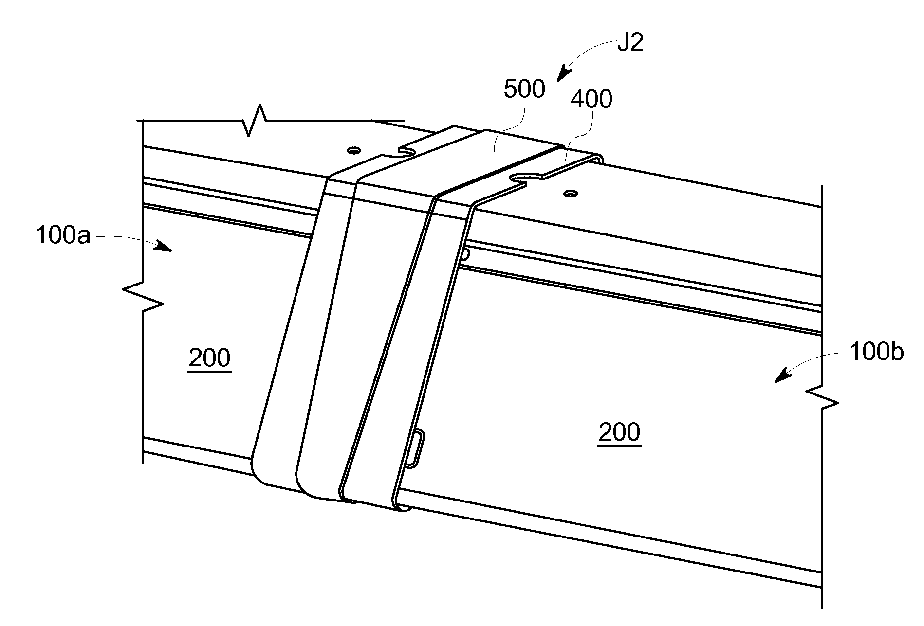
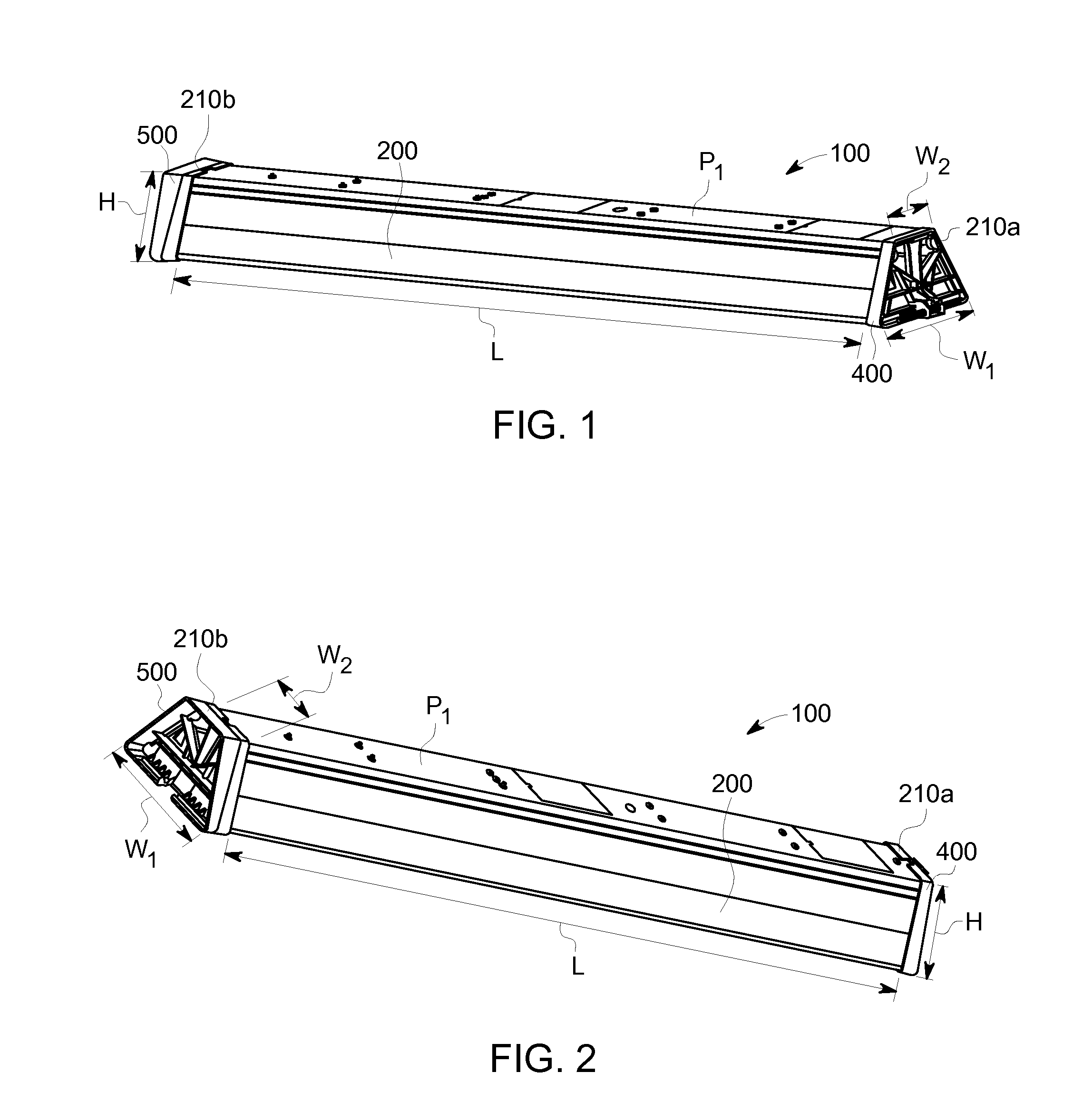
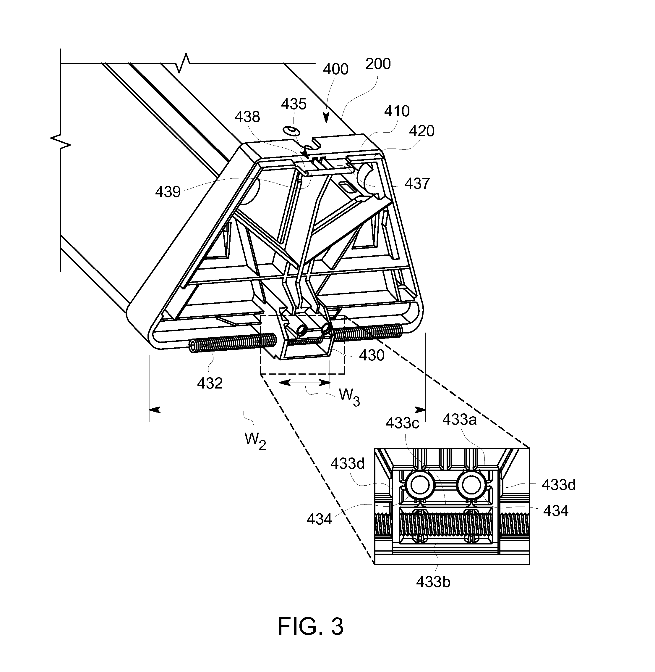
Provided is a lighting assembly comprising a pin end connector and a knuckle end connector. The pin end connector includes a protrusion having at least one wall and a rotational fastener configured to be received through and retained by the wall. The knuckle end connector includes a discontinuous seat having a first opening configured to receive the protrusion and a second opening configured to receive the rotational fastener. The pin end connector is configured to be received by the knuckle end connector and pivotally rotate to attach the first connector assembly with the second connector assembly. Also provided is a method for joining the pin end connector with the knuckle end connector.

Description

FIELD OF THE INVENTION[0001]The present invention is related to lighting fixtures. More specifically, the present invention is related to lighting fixture connector assemblies.BACKGROUND OF THE INVENTION[0002]Lighting fixtures, such as luminaires, can be suspended from a support, such as a ceiling, at a height that can be ten feet or more in the air from a ground surface. A lighting fixture is often connected to other lighting fixtures to form continuous rows. Typically, lighting fixtures are constructed of metal and are of moderate weight. While the lighting fixtures can have a relatively small cross-section, their length generally ranges from about 4-8 feet. These characteristics can make lighting fixtures difficult to handle.[0003]Particularly, the conventional process of assembling and installing lighting fixtures can be challenging, and require installers to engage in complex, dangerous and cumbersome installation processes. This conventional assembly requires several installer...

Claims


Application Information

Patent Timeline
Patent Type & Authority Applications(United States)
IPC IPC(8): F21V23/06
CPCF21V23/06F21V21/005F21S2/00F21S4/28F21S8/06F21V15/015
Inventor LUU, PHILIPPEMAGNAN, SEBASTIENWILSON, CHRISTOPHER HENRYYON, JEREMY WAYNE
Owner GE LIGHTING SOLUTIONS LLC
Learn More