
Method for Detecting Leaks In A Fuel Circuit of a Gas Turbine Fuel Supply System

a technology of gas turbine fuel supply and leak detection, which is applied in the direction of engine starters, fluid tightness measurement, instruments, etc., can solve the problems of fuel leaks around the fittings, loss of test pressure, and current process time-consuming, and achieve the effect of increasing the sound level

Active Publication Date: 2017-02-23
GENERAL ELECTRIC CO
View PDF5 Cites 41 Cited by
  • Summary
  • Abstract
  • Description
  • Claims
  • Application Information

AI Technical Summary

Benefits of technology

The invention has certain benefits that can be realized through its use. These benefits may include improving efficiency, reducing costs, or enhancing performance. The technical effects of the invention can be visible in various areas such as manufacturing, logistical operations, or customer satisfaction. Ultimately, the invention can help to solve certain problems or address certain challenges.

Problems solved by technology

During installation and / or over time, fuel leaks may be present or develop around the fittings.
Although effective, this leak detection process has a few drawbacks.
For example, one drawback is that the current process is time intensive.
As a result, if the tubes were connected the fuel circuit would depressurize when the pressure exceed 100 psig, thereby causing a loss of test pressure.
This may also mean that the final connection at the check or 3-way vales cannot be verified in the test.
In addition, testing at 500 psig and above, especially with compressible fluid, may require special safety considerations for technicians.

Method used


Image

  • Method for Detecting Leaks In A Fuel Circuit of a Gas Turbine Fuel Supply System
  • Method for Detecting Leaks In A Fuel Circuit of a Gas Turbine Fuel Supply System
  • Method for Detecting Leaks In A Fuel Circuit of a Gas Turbine Fuel Supply System

Examples


Embodiment Construction

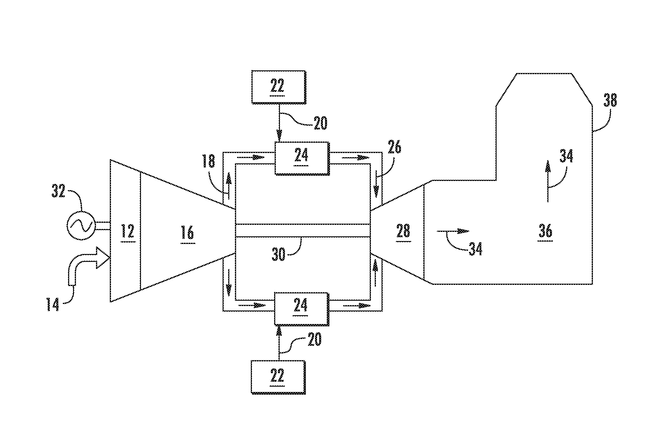
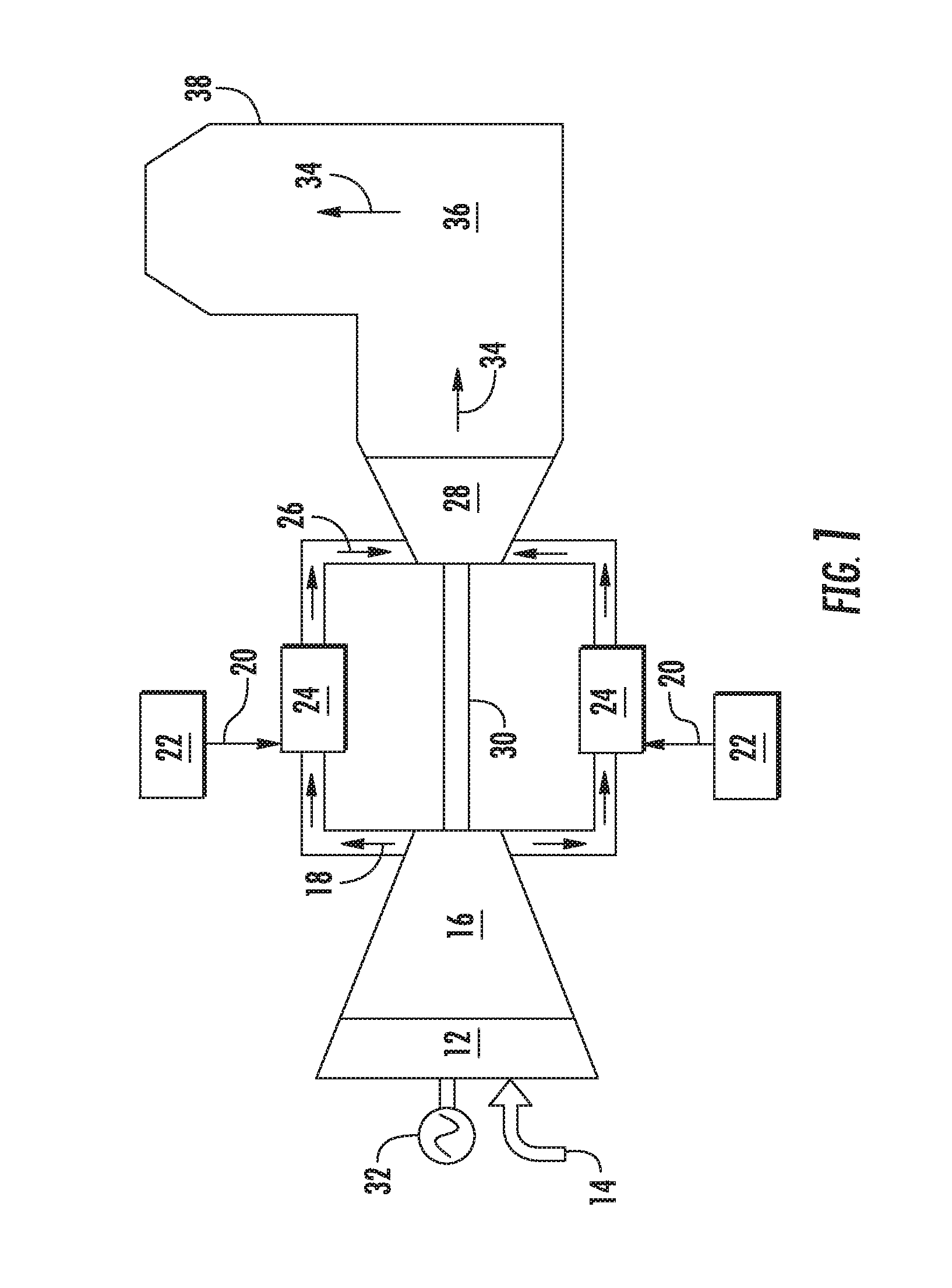
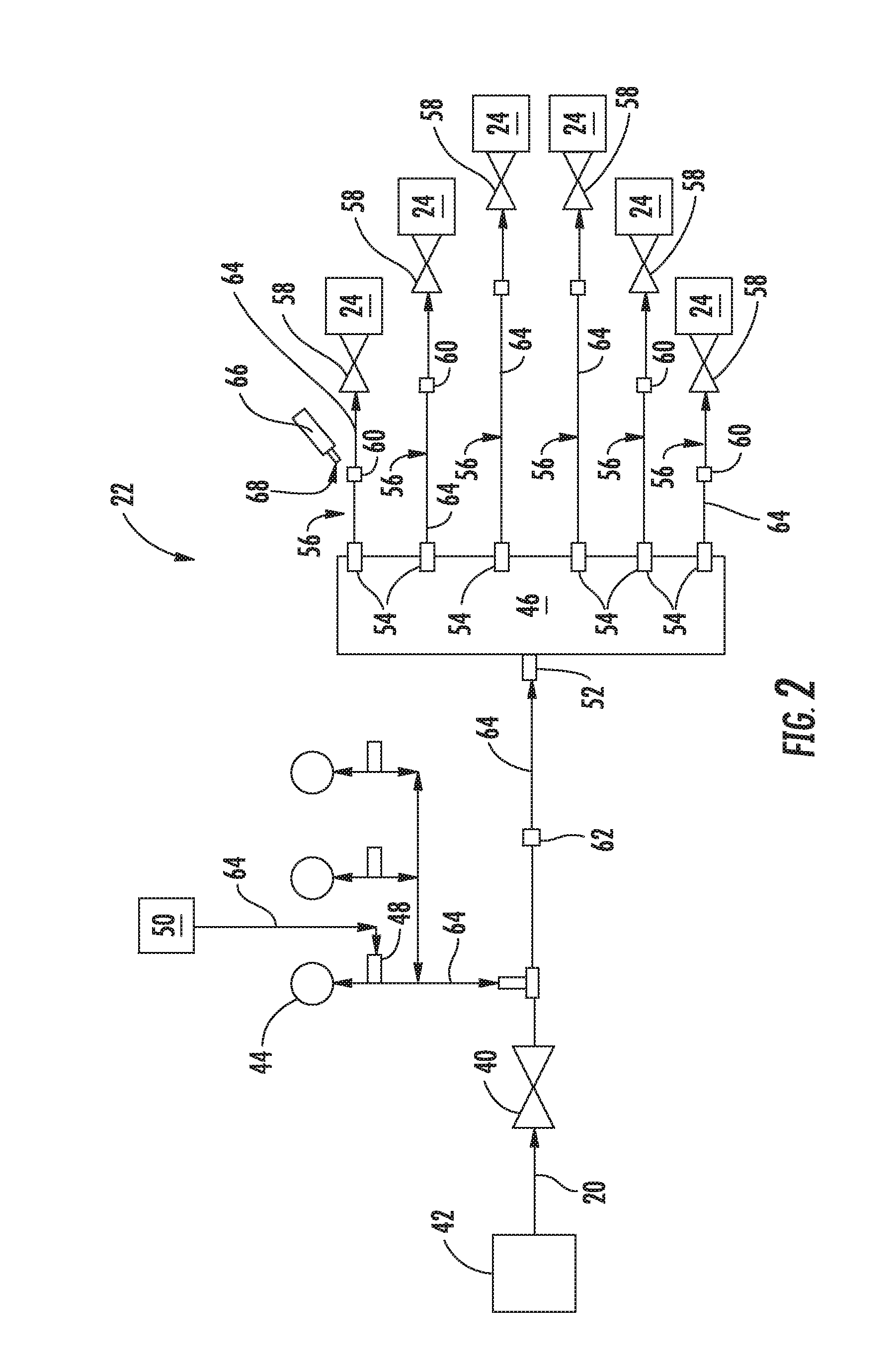
[0013]Reference will now be made in detail to present embodiments of the invention, one or more examples of which are illustrated in the accompanying drawings. The detailed description uses numerical and letter designations to refer to features in the drawings. Like or similar designations in the drawings and description have been used to refer to like or similar parts of the invention. As used herein, the terms “first”, “second”, and “third” may be used interchangeably to distinguish one component from another and are not intended to signify location or importance of the individual components. The terms “upstream” and “downstream” refer to the relative direction with respect to fluid flow in a fluid pathway. For example, “upstream” refers to the direction from which the fluid flows, and “downstream” refers to the direction to which the fluid flows. The term “radially” refers to the relative direction that is substantially perpendicular to an axial centerline of a particular compone...


PUM


Abstract

A method for detecting leakage at a fluid connection for a gas turbine fuel supply system is disclosed herein. The method includes closing a flow control valve at an upstream end of the fuel supply system and pressurizing the fuel supply system with a compressed medium via a compressed medium supply to a target pressure. The target pressure is less than a pressure threshold of a check valve that is disposed downstream from the compressed medium supply and upstream from a corresponding combustor of the gas turbine. The method further includes pointing a receiver portion of an ultrasonic detection device proximate to at least one tube fitting of the fuel supply system located between the flow control valve and a combustor which is fluidly coupled to the fuel supply system. Detection of an increase in sound level and / or the sound of popping at the tube fitting is indicative of a leak at the tube fitting.

Description

CROSS REFERENCE TO RELATED APPLICATIONS[0001]The present application claims filing benefit of U.S. Provisional Patent Application Ser. No. 62 / 207,639 having a filing date of Aug. 20, 2015, which is incorporated by reference herein in its entirety.FIELD OF THE INVENTION[0002]The present disclosure relates to a method for detecting leaks in a fuel circuit of a gas turbine fuel supply system.BACKGROUND OF THE INVENTION[0003]A gas turbine generally includes, in serial flow order, a compressor section, a combustion section and a turbine section. During operation, air enters the compressor via an inlet system and is progressively compressed as it is routed towards a compressor discharge or diffuser casing. The compressed air is routed into individual combustors of the combustion section. At least a portion of the compressed air is mixed with a fuel and burned within a corresponding combustion chamber defined within each combustor, thereby generating high temperature and high pressure comb...

Claims


Application Information

Patent Timeline
IPC IPC(8): G01M3/24G01M15/14
CPCG01M15/14G01M3/243F02C9/26G01M3/12G01M3/025F01D19/00F01D21/14F01D25/00F02C7/00F02C7/22F02C9/263F02C9/28F02C9/46F02K9/54F05D2260/80G01M3/007G01M3/26G01N29/14
Inventor FAQIHI, BOURIAKHALIQ, ABDULDEN OUTER, JAMES FREDERIKMOLDENHAUER, THOMAS EARNESTLYNCH, MICHAELEPLEY, RICHARD PRESTONCASTELLAW, STEVENZHENG, SHENG JIA
Owner GENERAL ELECTRIC CO
Learn More