Modular muffler

a module and muffler technology, applied in the field of mufflers, can solve the problems of inefficiency and cost, and achieve the effects of enhancing the level of sound reduction, reducing the cost of operation, and being strong and effectiv

Inactive Publication Date: 2006-10-05
KLAUS FREDERICK NOWAK ADVANCED CAR SPECIALTIES
View PDF12 Cites 13 Cited by
  • Summary
  • Abstract
  • Description
  • Claims
  • Application Information

AI Technical Summary

Benefits of technology

[0010] The muffler should preferably be configured so that it can be modified, at a time after it has been manufactured and sealed closed, to obtain a higher degree of sound absorption or attenuation. Preferably, the modification can be done quickly and easily, and from outside the muffler so that the muffler would not have to be opened. The modification will preferably be sufficiently strong and effective so that it is permanent, unless the user wishes to remove the modification, without requiring further action to maintain the enhanced level of sound reduction. It is also preferable that the muffler be capable of manufacture using standard production methods.
[0011] The muffler will preferably be modular, comprising a base muffler having an intrinsic sound reducing capability, and a sound reducing element that can be inserted into or attached to the base muffler, to further reduce the sound output of the muffler. By selecting from different sound reducing elements spanning a range of attenuation levels, the sound reduction capability of the muffler can be improved to a predetermined level without making any changes to the base muffler.
[0012] Accordingly, there is provided an exhaust gas muffler for an engine, said exhaust gas muffler having a body; at least one inlet for said exhaust gas from said engine on said body; a chamber in said body to receive exhaust gas from said at least one exhaust gas inlet and to reduce a sound of said exhaust gas; and at least one exhaust gas outlet from the chamber to vent said exhaust gas from said chamber, said exhaust gas outlet being sized and shaped to receive a sound reducing element from outside of said muffler, wherein, by attaching a sound reducing element to said muffler, said muffler can reduce said sound of said exhaust gas to a predetermined level.

Problems solved by technology

Further, since exhaust gases are usually extremely hot and move under pressure at high velocity, the muffler chambers are almost always very tightly sealed by thorough welding or mechanical forming of joints and seams.
Since each muffler must be separately designed, produced, and distributed, this is costly and inefficient.

Method used


Image

  • Modular muffler
  • Modular muffler
  • Modular muffler

Examples


Embodiment Construction

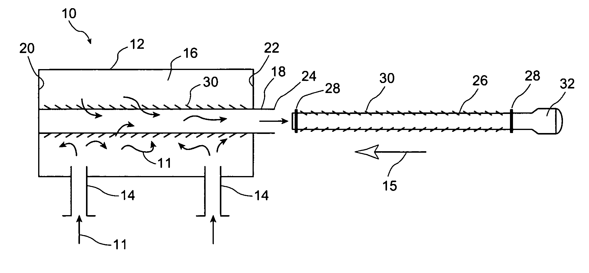
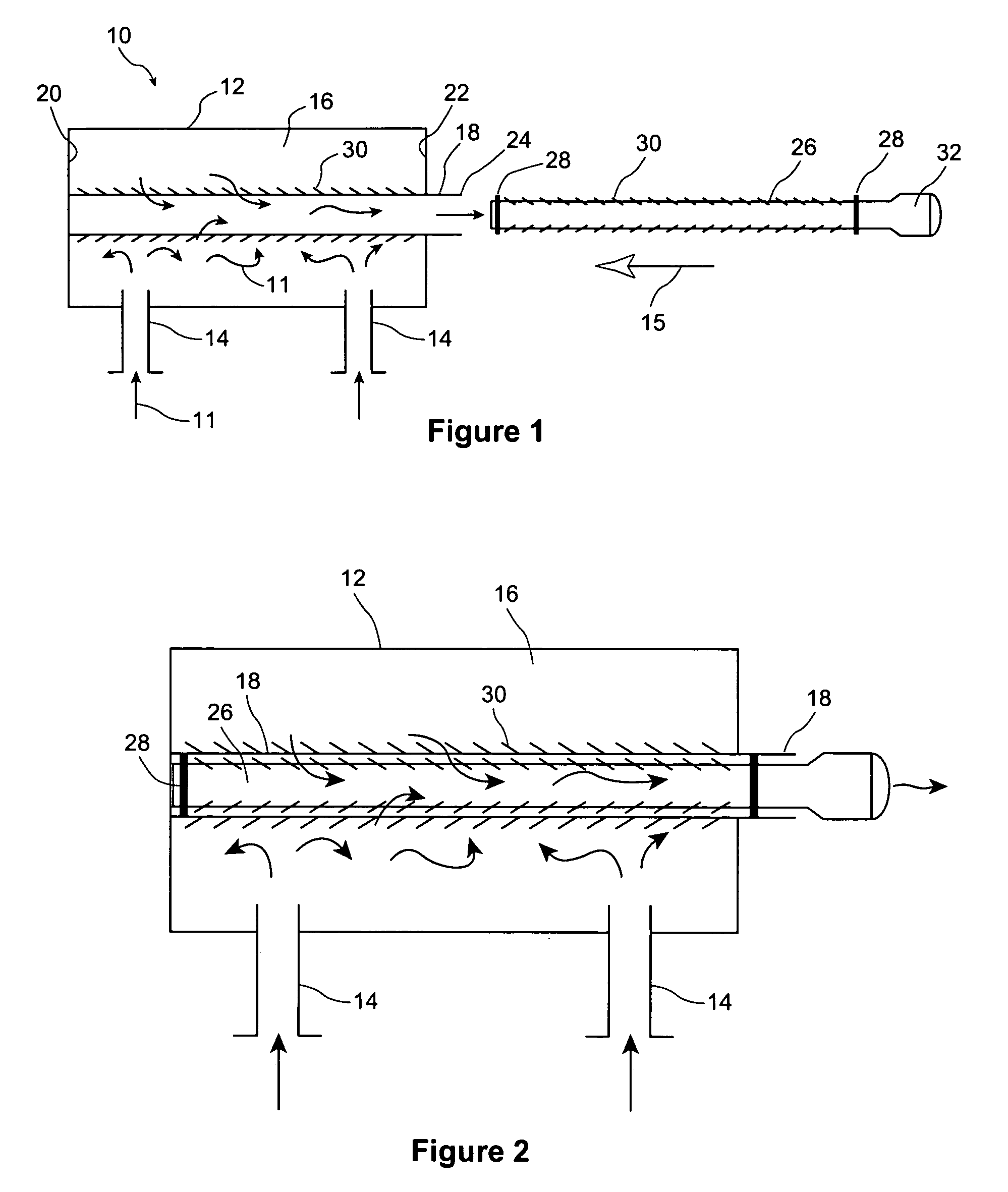
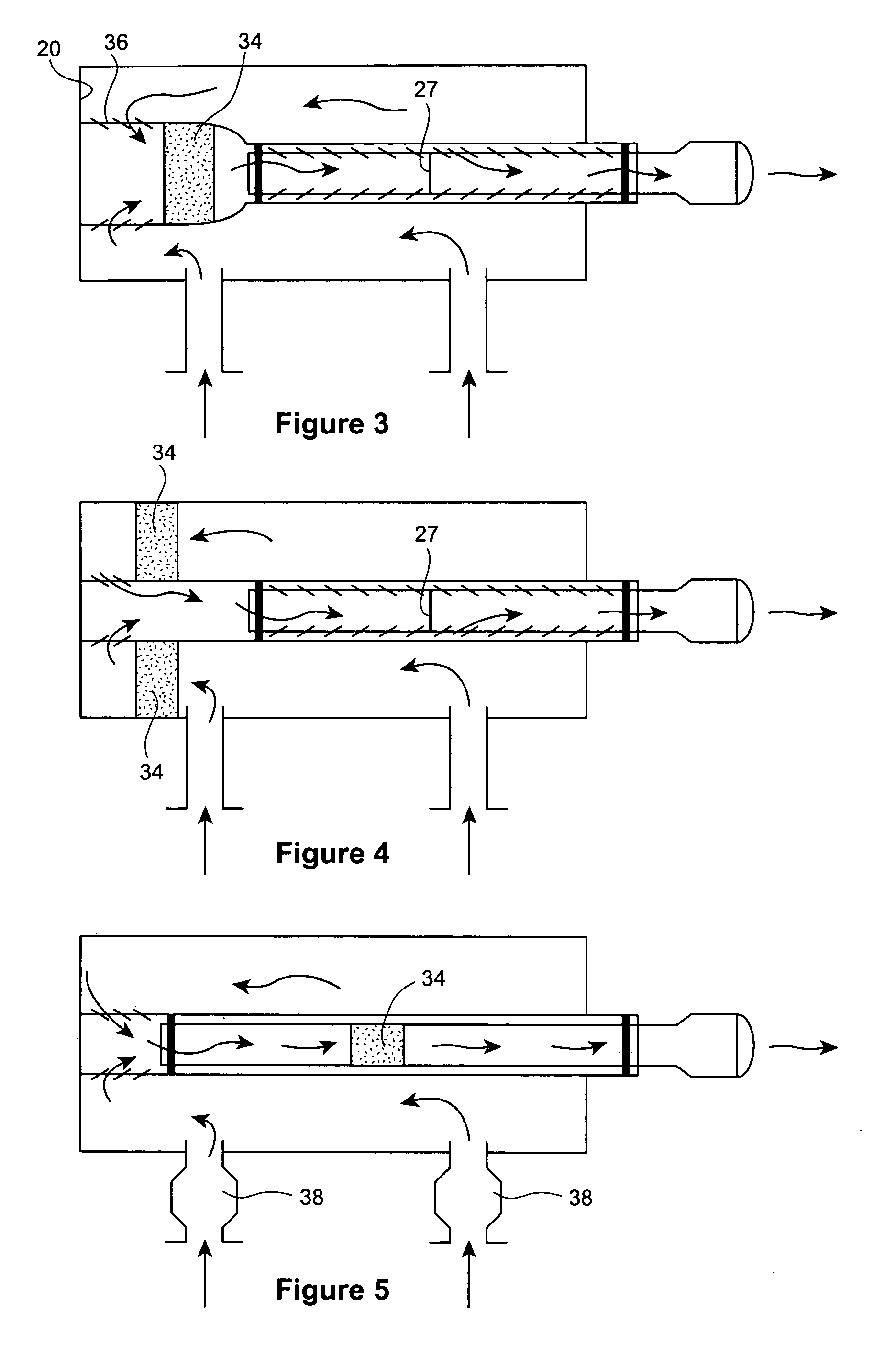
[0019] The modular muffler or exhaust gas muffler of the present invention is shown in a side view in FIG. 1 and generally designated as 10. The muffler 10 receives exhaust gas 11 from an engine (not shown). The muffler 10 generally comprises a base muffler or body 12 having at least one exhaust gas inlet 14, an internal chamber 16 to receive the exhaust gas 11 from the inlet 14, and at least one exhaust gas outlet or tailpipe 18 to vent the exhaust gas from the chamber 16. In the embodiments shown in FIGS. 1-5 there are two exhaust gas inlets 14. The chamber 16 has a first or back wall 20 at one end and a second or front wall 22 at the other end. In the figures the tailpipe 18 is attached to back wall 20, and extends the length of the chamber 16 past front wall 22 to a termination point 24 outside of body 12. The tailpipe 18 is usually configured as a tube or conduit, although other embodiments are also comprehended by the present invention.

[0020] The muffler 10 also includes a so...


PUM


Abstract

An exhaust gas muffler for an engine, the exhaust gas muffler having: a body, at least one inlet for the exhaust gas from the engine on the body, a chamber in the body to receive exhaust gas from the at least one exhaust gas inlet and to reduce a sound of the exhaust gas, and at least one exhaust gas outlet from the chamber to vent the exhaust gas from the chamber, the exhaust gas outlet being sized and shaped to receive a sound reducing element from outside of the muffler, wherein, by attaching a sound reducing element to the muffler, the muffler can reduce the sound of the exhaust gas to a predetermined level.

Description

CROSS-REFERENCE TO RELATED APPLICATIONS [0001] Not applicable. STATEMENT REGARDING FEDERALLY SPONSORED RESEARCH [0002] Not applicable. FIELD OF THE INVENTION [0003] This invention relates to the general field of exhaust systems, and more particularly to mufflers used with internal combustion engines. BACKGROUND OF THE INVENTION [0004] Internal combustion engines generate by products of combustion often referred to as exhaust gases. Typically, for noise control the exhaust gases pass through a muffler and tailpipe before being released. Such engines and their associated exhaust systems are ubiquitous, being used to power all types of motor vehicles as well as smaller, more specialized vehicles and devices such as, for example, golf carts, all-terrain vehicles (ATV's), utility vehicles, lawn tractors and mowers, power generators, and other turf and industrial equipment. [0005] The degree of sound absorption or muffling performed by a particular muffler will vary depending on the type ...

Claims


Application Information

Patent Timeline
Patent Type & Authority Applications(United States)
IPC IPC(8): F01N1/08
CPCF01N1/08F01N2260/14F01N13/082F01N1/10
Inventor SOUTHWAY, NIGELPELKONEN, ARNE
Owner KLAUS FREDERICK NOWAK ADVANCED CAR SPECIALTIES
Why Eureka
Try Eureka